Home | Contact Us | Submit Troubleshooting Info | Search | Help


    Output | Software Solutions | Proofing | Color, Screening and Calibration | Scanning | Digital Photography | Consumables | POS


Dolev 800 - Loading/Unloading System -
- Detectors & Switches

Listed By Type
Listed By Function
Cassette In Detectors (#1,2,3)
Cassette "No Film" Detectors (#1,2,3)
Cutter Position Detectors
Lever Detectors
Film In/Out Detector
Film Spreader Home & End Position Detectors

Listed By Type

Optically Slotted Switches
Magnetic Read Switches

Optically Slotted Switches

On the Loading System Film cutter right (#290B29520)
Film cutter left

The film cutter switches are located at the home position left and right. They are assembled on the cutter carriage.

On the Roller Roller position encoder
Roller home
Roller end

On the Carriage Carriage right
Carriage left

Feeder Roller Wheels Film length encoder right
Film length encoder left

Magnetic Read Switches

On the Loading System:

Listed By Function

Feeding System (Lever-type Switch)
Sensing Output Cassette
Conveyor (Lever-type Switch)
Load Door Switches
Vacuum System
Interlock Switch

Feeding System (Lever-type Switch)

Film in right (on the V-guide at entrance to drum)
Film in left (on the V-guide at entrance to drum)

Sensing Output Cassette

The Output Cassette Present is a Lever-type Switch.

Conveyor (Lever-type Switch)

Film in conveyor, right
Film in conveyor, left
Film out conveyor, right
Film out conveyor, left

Load Door Switches

Upper loading door (part of the mainframe)
Lower loading door (part of the mainframe)

Vacuum System

Note: Not in use.

-Two switches for detecting vacuum suction
- Detects open Valve: A or B, or, A and B

Interlock Switch

intloksw.gif (6836 bytes)
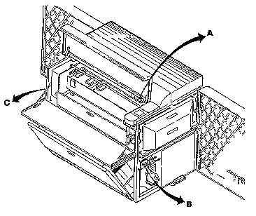
The Dolev 800 has 3 interlocks (A,B,C) which cut off power to certain parts of the imagesetter when the left or right side service doors are opened or when the Loading system is removed from the Imagesetter. All Imagesetter operations are disabled when an interlock is activated or impaired.

Cassette In Detectors (#1,2,3)

Loading System - Type I (zoom image)
Loading System - Type II (zoom image)

Description
Replacement
Check

Description

The Cassette Film-In Detectors are located on the Film Loading Assembly. There are three Cassette Film-In Detectors, one for each cassette. They are activated by a magnet that is attached to the inside of the cassette. The pulse allows the machine to recognize that the cassette is present.

Replacement

Follow the steps for Removing the Loading and Unloading Unit.

  1. Unfasten the four detector cover screws (#143).

  2. Remove the detector cover (#142)

  3. Using the Diagnostics Utility, identify the cassette (1, 2 or 3) which has the defective detector. (Enter the diagnostics program by selecting UTILITIES, MECHANICS. Select 9. Detectors from the Mechanics Menu.)

    Mechanics Menu
    1. Carriage 2. Roller 3. Spinner
    4. Cassette 5. Feeder 6. Cutter
    7. Vacuum/Valve 8. Others 9. Detectors

  4. In the case of a defective detector in cassette # 1 or 2, replace the right detector by unfastening the two detector screws (#80).

    In the case of a defective detector in cassette # 3, replace the left detector by unfastening the two detector screws (#80).

  5. Fasten the two detector screws (#80).
    Re-install the detector cover (#142)

    Return the loading system back to its place and close the lockers.

  6. Power on the imagesetter.

  7. Re-Enter the diagnostics program. Select UTILITIES, MECHANICS. Select 9. Detectors from the Mechanics Menu. Check for accurate results.

Check

  1. Enter Diagnoscontent/Utility/Detectors.

  2. Remove and Insert the Cassette and see the response. The flag should toggle between off and on.

Cassette "No Film" Detectors (#1,2,3)

Loading System Base - Type I (z12) (zoom image)
Loading System Base - Type II (zoom image)
Loading System Base - Dolev 800 P (zoom image)

Description
Replacement
Check

Description

The Cassette "No Film" Detectors are located on the Film Loading Assembly. There are three Cassette "No Film" Detectors, one for each cassette. They are activated by four magnets that are attached to the Cassette Central Shaft. The pulses are counted to the Cassette NVM and this information allows the operator to be aware that no film remaining in the cassette.

Replacement

Follow the steps for Removing the Loading and Unloading Unit.

  1. Unfasten the four detector cover screws (#143).

  2. Remove the detector cover (#142)

  3. Using the Diagnostics Utility, identify the cassette (1, 2 or 3) which has the defective detector. (Enter the diagnostics program by selecting UTILITIES, MECHANICS. Select 9. Detectors from the Mechanics Menu.)

    Mechanics Menu
    1. Carriage 2. Roller 3. Spinner
    4. Cassette 5. Feeder 6. Cutter
    7. Vacuum/Valve 8. Others 9. Detectors

    In the case of a defective detector in cassette # 1 or 2, replace the left detector by unfastening the two detector screws (#80).

    In the case of a defective detector in cassette # 3, replace the right detector by unfastening the two detector screws (#80).

  4. Fasten the two detector screws (#80). 77
    Re-install the detector cover (#142)

    Return the loading system back to its place and close the lockers.

  5. Power on the imagesetter.

  6. Re-Enter the diagnostics program. Select UTILITIES, MECHANICS. Select 9. Detectors from the Mechanics Menu. Check for accurate results.
       
    Mechanics Menu
    1. Carriage 2. Roller 3. Spinner
    4. Cassette 5. Feeder 6. Cutter
    7. Vacuum/Valve 8. Others 9. Detectors

Check

In order to check this detector, load film from the cassette which needs checking and make sure that the message "No Film" does not appear.

Make sure that "Laser Beam" is set to 1 in the plotter description setting table. If it is set at "0", the detector will not work.

Cutter Position Detectors

Description
Replacement
Check

Description

The cutter position detectors are located at the front of the loading system, under the cutter shaft. The detectors are opto-switches and they detect the left and right position of the cutter movement.

Replacement

Before You Start
Tools and Accessories
Disassembling the Cutter Position Detectors
Assembling the Cutter Position Detectors

  • Before You Start

    1. Switch off the power to the machine via the operation panel switch.

    2. Open the side doors and the light proof covers.

    Tools and Accessories

    Set of Allen Keys

    Disassembling the Cutter Position Detectors

    1. Open the loading system doors and pull out the three film cassettes.

    2. Open the lockers of the loading system and pull the loading system out as much as you can while not pulling it off the tracks. Do not pull the loading system completely out of the machine.

    3. Disconnect the connections to the detector.

    4. Move the cutter housing away from the detector if it is interfering with the work.

    5. Open the Hd cap st-st #6-32 x 1/2" screw that holds the detector to the bracket.

    Assembling the Cutter Position Detectors

    1. Assemble the new detector on the bracket with a #6-32 x 1/2" screw.

    2. Connect the connector to the detector.

    3. Push the loading system into the main frame and close the lockers. Place the film cassettes add and close the loading system doors.

    4. Close the light shade covers and the side doors.

    Check

    1. Enter the Diagnostics/Utilities and choose the Detectors menu.

    2. Check if the cutter position detectors are functioning. (Pressing the letter that appears near the relevant detector will activate it.)   

    Lever Detectors

    Loading System - Type I (zoom image)
    Loading System - Type II (zoom image)

    Description
    Replacement
    Adjustment
    Check and Test

    Description

    The lever detectors (Cat No. 314A00010) are located on the loading system. The lever closes the gaps between the medium film rollers and the small film rollers. The detectors are responsible for distinguishing between closed rollers or open ones.

    Replacement

    Before You Start
    Tools and Accessories
    Disassembling the Lever Detectors
    Assembling the New Lever Detector

    Before You Start

    1. Power off the Imagesetter using the control panel ON/OFF switch.

    2. Open the side service doors and remove the protective covers.

    3. Free the top of the Lift-O-Mat pistons on both sides of the Imagesetter. To do this, remove the E-ring that secures the piston to the frame.

    Tools and Accessories

    Set of Allen keys
    Phillips screw driver

    Disassembling the Lever Detectors

    1. Open the loading system compartment doors.

    2. Remove the light-proof covers from both sides of the unit.

      Note: If the problem is with the right detector, you do not need to disconnect the electronic harness cable connectors on the right side of the Imagesetter. Removing the light-proof covers is enough.

    3. Remove the E-ring that secures the top of the left lift-o-mat piston. Tilt the piston downwards.

    4. Open the two track locks on each side of the system.

    5. Grasp the handles from both sides and gently pull the system forward 10 cm.

    6. Disconnect the connector from the detector.

    7. Remove the two screws that hold the detector.

    Assembling the New Lever Detector

    1. Put the new detector in place. Tighten the two screws that hold the detector. Maintain a gap of 2 mm while the lever is in the closed position.

    2. Reconnect the connector to the detector.

    3. Assemble the connector holder back into place.

    4. Slide the loading system in place. Close the track locks.

    5. Return the loading system back to its place and close the lockers.

    6. Put the film cassettes back in their compartment.

    Adjustment

    1. Enter the Dolev 800 Diagnostics under UTILITY / DETECTORS

    2. Press the number / letter next to the relevant lever (either upper or lower lever)
         
    3. Make sure that the relevant lever is in the CLOSED position.

    4. Release the two screws that hold the magnets to the base and move them forwards and backwards until you receive a steady ON message.

    5. Tighten the two screws in the correct position.

    6. Open and Close the lever several times and make sure that the reading is good.

    Check and Test

    1. Power on the Imagesetter.

    2. Activate the DIAG/UTIL in the detectors menu. Move the lever from the OPEN position to the CLOSED position and see if it activates the detector.

    3. Close the light-protective covers, the side service doors, and the loading system doors.

    Film Spreader Home & End Position Detectors

    OptoMechanical Assy (zoom image)
    Optomech 800P (zoom image)

    Description
    Home and End Position Detector Replacement

    Description

    The film spreader position detectors (#2) are photo interrupters. They are located on the optomechanical assembly. The detectors are on the left side of the machine, on the lower part of the drum.

    Home and End Position Detector Replacement

    Before You Start
    Tools and Accessories
    Disassembling the Detectors
    Assembling the Detectors
    Check

    Before You Start

    1. Power off the imagesetter using the control panel ON/OFF switch.

    2. Open the left service door.

    Tools and Accessories

    Set of Allen keys
    Phillips screw driver
    Flat open keys set

    Disassembling the Detectors

    1. The sensor plate (#17) has two detectors. The End Position detector is on the right. The home Position detector is on the left.

    2. Disconnect the connector from the detector.

    3. Dismantle the detector from the base by releasing the two screws (#13,14,15,16).

    Assembling the Detectors

    1. Assemble the new detector with the 6x32 x 5/8" screw. Return it to the original position: the flag passes in the center of the detector slot.

    2. Activate the Diag/UTIL in the detectors menu and by moving a little bit forward and backward the film spreader flag (only from the left side of the machine to avoid twist in the film spreader shaft). See if the detector functions. (Choose Detectors on Mechanics Menu)

    Check

    1. Check that the detector flag is positioned correctly:

      Home Pos. Moves Roller toward Home Position.
      End Pos. Moves Roller toward End Position.

    2. If the flag is not in the center of the detector, open the screws 8x32 x 8/8" and move it to the center until you will see a response from the detector.

        Copyright © 2005 Creo Inc. All rights reserved. Confidential. Back to top.