

Home | Contact Us | Submit Troubleshooting Info | Search | Help
Output | Software Solutions | Proofing | Color, Screening and Calibration | Scanning | Digital Photography | Consumables | POS
Home | Contact Us | Submit Troubleshooting Info | Search | Help
Output | Software Solutions | Proofing | Color, Screening and Calibration | Scanning | Digital Photography | Consumables | POS
Dolev 800/800V/800V² TIC - Installation
Connect & Set Up Host
Powering On/Off the
Machine
Setting up the Configuration
Setting
Date, Time and Measurement Units
Diskette Drive Operation
Powering On the Imagesetter
Powering Off the Imagesetter
In normal operation, you power on the imagesetter by pressing the On/Off switch located to the right of the Control Panel.
Press the On/Off switch on the control panel. You receive a
message on the panel,
==All Tests Passed==.
The panel LCD contains several menus, each of which handles a Dolev 800 operation. When you power on the imagesetter, a startup screen displays the word Startup and a number from 001 to 012. The number represents one of the initialization tests. This information is helpful if the imagesetter becomes stuck during startup. The number provides the service engineer with an immediate indication of the stage at which a problem occurred. At the end the word "Standby" will be shown on the cassette's status bar's panel.
Wait 15 minutes before exposing your first film. The time is required for the laser system to warm up.
Note: If you press the On/Off switch and the imagesetter does not power on, perform the following:
The Dolev 800 is left operational under normal conditions. You do not need to turn off the power overnight. If you leave the imagesetter idle for 48 hours, you should power off the imagesetter from the On/Off switch on the control panel.
The control panel is located on the top right front edge of the Dolev 800. To the right of the panel is an On/Off switch.
Starting System Configuration
Station Configuration
I/O Devices Configuration
I/O Devices Plotter
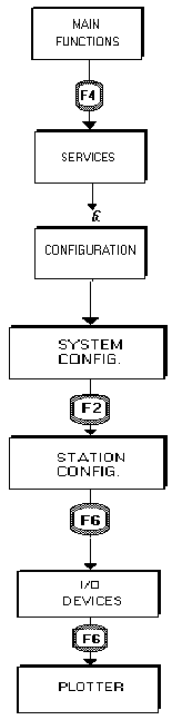
1. Main Functions
2. F4
3. Services
4. configuration
5. System configuration
6. F2
7. Station Configuration
8. F6
9. I/O Devices
10. Plotter
The Dolev 800 must be configured within the CreoScitex Color Workstation before you begin work. Usually, a CreoScitex engineer configures your system during installation.
To move down a list of I/O station menu options, use the Down arrow key. In most configuration screen fields, there are a limited number of options. On I/O stations, press the Space Bar to toggle a field. A field that you can cycle through has the character "" appearing as the first character in the field. All numeric fields are cyclical.
Configuration defines your Dolev 800 imagesetter, the workstation connected to your imagesetter, and how they are connected. The station that you are working on is called the Local Station.
You begin from the I/O station Main Functions menu:
| Form Input Fields | |
| Workstation Type [toggle field] |
Your workstation is listed on the form. The station is the Whisper/microWhisper unit. Toggle to: I/O, Assembler, etc. |
| Station Name | The station is the Whisper-based unit. The Local station is your workstation: Assign a logical name to your station. |
| Network | Check that your network connection is registered. Select Station Config <F2>. |
Select Station Config (F2) and the Station Configuration Screen will appear.
Station Configuration displays the I/O Devices softkey (F6) to define Dolev 800 within the system. The Station Configuration form for your station appears. The station name is the name you entered earlier on the System Configuration form. You can also define the fiber optics board and any additional devices.
Select the I/O Devices soft key (F6) on the Station Configuration form.
When you select I/O Devices <F6> on the Station
Configuration form you can configure the imagesetter connected to your station.
Select Plotter (F6) on the Configuration form.
Soft Keys (F-KEYS)
Save & Exit (F1)
Save your entries and Enter (F4)
Saves your entries and returns you to the
previous configuration form.
Main Menu <F5>
Returns you to the System Configuration form.
Next <F7>
Displays the next form.
Quit <F6>
Return to the Main Functions Menu without
making any changes.
From the I/O Devices:Plotter form, toggle the plotter field until you reach the Dolev 800. Select Enter (F4) to choose the Dolev 800 imagesetter.
Press the SPACE BAR until you receive Dolev 800.
The options are: Dolev 800, RAYSTAR, RAY RECEIVE, RAYTRANS, RAYTRANS+, DOLEV, DOLEV-HR, DOLEV 400, THINK, CHEMCO, STORK and NO.
Size [H,W]
The maximum output size, 812 H x 1117 W appears automatically. You can reduce the size.
Select Save & Exit to save any changes.
General
Time and Date
Unit Defaults Setting
Color Units
The Set Up option contains all of the setting menus needed to set time, date and measurement units.
Select Set Up (F2) from the Main Functions menu.
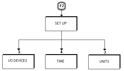
The time and date are usually set for the system. If you need to change these for any reason, select Time (4.) on the Set Up menu. The time and date appear next to the file name on the Whisper system full library list. You can print the time and date as part of the label on exposed films. Follow the instruction on the form.
When you complete the form, select Enter (F1).
Use the Units option to define measurement units and color values.
Select Set Up (F2) from the Main Functions menu soft keys.
Select 7. Units from the Set Up menu, the following form appears on the screen:
Press the Space Bar to Change "Size" Units from the default unit, millimeters, to inches. Press ENTER key to skip to the "Color Units" field.
The possible system color values are density, percentage, or system values. Press the Space Bar (on the cursor for interactive systems) to change the Color Units from the default.
| Enter Density: | The film
density of each separation can be defined within a range of upper and lower
limits (Dmax and Dmin). CreoScitex allows you to enter values from zero
(0) in the highlights to 400 in the shadows. We recommend, however, that
the minimum density be set to 25. The recommended maximum is 170. The 25-170 density range is equivalent to density values 0.25 to 1.7. When you select Density, you receive max 0.00/min 0.00. Enter the maximum and minimum density values. |
| Enter Percentage (of Dots on Separation) | |
| The Percentage of dots on the separation can have a range of 0% highlights to 100% shadows. | |
| Enter System Values: | The CreoScitex
system sets a digital value corresponding to a density or dot area. When
a picture is scanned into the system, the optical density of the picture
is converted into voltages. The system converts the analog voltages into
256 distinct system values. Range: 255 (highlights) to 0 (shadows). |
| Exit Color Unit Definition: | When you finish, select Save & Exit (f1). |
A 3.5 inch floppy diskette drive is located in front of and below the panel. The floppy diskette is inserted in the disk drive before the imagesetter is powered on. The floppy loads all of the information the imagesetter needs for normal operations. Do not remove the diskette from the machine unless instructed by your supplier.
The panel is designed to work in two modes, Exposure Mode or Diagnostics Mode.
| Exposure Mode: | Set Loading assists
you during the loading process. During the loading process, the section of media exposed to light during loading must be cut. Set Loading automatically cuts the exposed media and disposes of it in the output cassette. For this reason, be sure that the output cassette is empty before you load a new supply cassette onto the imagesetter. During an exposure, the control panel displays the percentage of the exposure completed. The operator uses the panel in two cases. The first case is when changing media types. The operator updates the imagesetter with the new media information. |
| Diagnostics Mode: | The second
case is when there is a machine failure. The operator has the option of
calling CreoScitex Service, or using the Diagnostics diskette. a) Press F1 (UTIL) on the control panel. b) Select Diagnostics. Insert the 3.5 inch floppy diskette into the drive and run the diagnostics. The diagnostics help isolate the problem. Depending on the nature of the problem, you either perform the troubleshooting or consult the CreoScitex Service Engineer. |