Home | Contact Us | Submit Troubleshooting Info | Search | Help
Output | Software Solutions | Proofing | Color, Screening and Calibration | Scanning | Digital Photography | Consumables | POS
Home | Contact Us | Submit Troubleshooting Info | Search | Help
Output | Software Solutions | Proofing | Color, Screening and Calibration | Scanning | Digital Photography | Consumables | POS
Dolev 800/800V/800V² TIC - Installation
Setup
Open
Doors and Level the Imagesetter - Adjustment Mounts
Remove
Shock Absorber Shipping Screws
Remove
Loading/Unloading System Shipping Screws
Remove/Store
the Optics Carriage Transport Locking Pin
Remove
the Film Spreader Locking Clamp
Replace Covers
and Close Doors
Storage
of the Pallet and Transport Bolts
Voltage Setting
Use the level adjustment mounts to fix the imagesetter in a level position. The mounts are similar to those found on home refrigerators To set the mount, loosen the top hex lock nut. Next, turn the bottom hex nut to raise or lower the mount to the required height. When the adjustment is complete, tighten the top hex nut to lock the mount.
It is best to adjust the height of each of the four mounts before you lock any of the mounts in place. Lock the mounts only when all four sides are set to the proper height.
Remove the black light-proof covers (#26 on Main Frame) on the top left and right of each side of the machine.
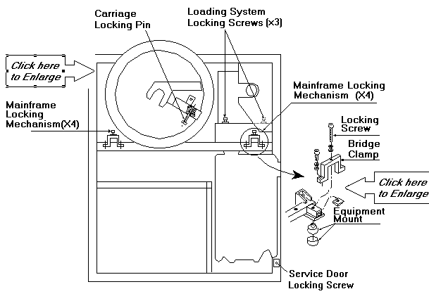
Locate the four shock absorber braces refer to figure 2.1-5) lue color. During shipping, a screw is installed through a metal brace (#16 on Top Assembly) and onto the drum frame. It distributes weight more efficiently for transport. You must remove the screw (#12,13,14) that places the weight of the drum on each brace.
Caution: Do not remove the screws securing the brace to the base of the machine (#15,6,7 on figure
Repeat the step above for all four shock absorber braces.
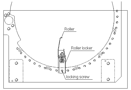
Locate the three (3) screws that secure the Loading/Unloading system during shipment. Remove the four screws.
Locate the optics carriage transport locking pin. The plastic pin is screwed through the bottom of the carriage guide. The pin is inserted 60 cm to the right of the carriage home position detector. Place the pin in a secure place inside of the machine for future use.
Put back the light-proof covers. Put back and close the left and right and left service doors. Put back the service covers at the rear of the imagesetter.
Do not dispose of the pallet. Screw the bolts used to secure the imagesetter to the pallet back onto the pallet. Store the pallet in a safe place.
Check the local voltage setting and connect the electrical cables.
Caution: No connections are to be made until voltage setting is complete!
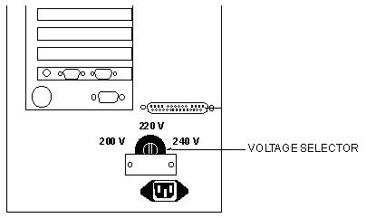
Before installation, match the line voltage with the voltage set for Dolev 800. Dolev 800 is sent from the factory oriented to 220 V. Perform the voltage setting below. Be sure that the ON/OFF switch on the Operation Panel and the Master circuit breaker switch at the rear of the imagesetter are both turned to the OFF position.
Voltage Selector on the Standard Controller