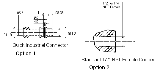
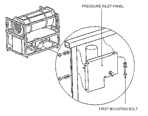
Refer to: Air Pressure Inlet Connector
Air Pressure Inlet Panel
Turn off the Imagesetter.
Ensure that the customer has prepared a 7 atm (100 psi)
compressed air pressure line. If a compressor line was prepared, check that its ratings
are:
7 - 10 atm (100 - 140 psi) minimum
Vessel volume of 20 liters (approximately 5 U.S. gallons)
Compressed air volume discharge rate of 3.6 m3/h (2 cfm) minimum
Check that the compressor outlet connector mates properly with
the Dolev 800 air supply system inlet connector. Connector details and options are
depicted in Do not activate the air compressor yet.
Warning: Connector Option 1, depicted in the accompanying figure, can be used
temporarily for direct connection to a rubber tube. However, this alteration should be
avoided after the installation! Connect to Option 1 only as a last resort.
Locate the three (3) cable connector plugs tied to the frame.
They are labeled: PUNCH, UNIT IN, and JAM OUT ON.
Take the Pneumatic and Control Unit from the punch kit and
insert the above three (3) connectors into their matching valve connectors on the Unit as
follows:
Imagesetter Cable Label
Panel Pressure Valve
Label
PUNCH
UNIT IN
JAM OUT ON
P
U
SLUG
Note: On some machines the cables are labelled
incorrectly. Should you receive a PUNCH ... STUCK error message when first operating the
punch system, try rerouting the cables. No damage will result. You will need to restart
the Imagesetter in order to release the software from this error condition. Review current
FCOs for additional details regarding this problem.
Remove the stopper plug from the pressure inlet elbow on the
Pneumatic and Control Unit by applying even pressure on the red ring encircling the plug
and pulling outward. Insert one (1) 8 mm orange tube edge into the pressure inlet elbow.
Attach the Pneumatic and Control Unit temporarily to the main
frame using only one of its three (3) mounting three bolts. This bolt is marked as the
First Mounting Bolt in During installation, the unit can be pivoted on this bolt for
easier access to tube connections.
Connect the other end of the 8 mm orange tube to the outlet on
the pressure regulator side.
Leaving the five plugs inserted in their ports on the
Pneumatic and Control Unit, activate 7 atm (100 psi) of air pressure and check for air
leakage. If there are no leaks, proceed to the next step.
Disconnect the air pressure if you hear a hissing sound from any point along among the
tubes, or if a tube pulls free of its connector. Recheck all connections. Tubes are
removed from their plugs by pressing evenly around the surface of the red inlet ring at
the base of the plug, and pulling the tube out.
Once the air pressure routing is free of leaks, deactivate the
air pressure and remove the five (5) remaining plugs from their ports on the Pneumatic and
Control Panel.
Locate the five (5) blue tubes located near the two vacuum
valves and insert them into the Pneumatic and Control Unit ports as follows: