Solution |
|
The align and spiral pins have to be repositioned on the Lotem 800 VL
drum because it is larger than the Lotem 850 drum.
To accommodate the larger drum size, it is necessary to drill holes into
the Lotem 800 VL drum and replace the existing head grippers, spring spoilers
and align and safety pins.
|
Procedure |
|
This procedure comprises of the following steps:
Preparing the Lotem 800 VL drum for new
spring spoilers and pins
- Open the front and rear doors of the platesetter via Lotem Controller.
- Remove the unloading tray.
- Shut down the platesetter via Lotem Controller.
- Move the tail gripper to preload position.
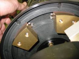
- On each side of the drum, manually move the two dynamic balance weights
until they touch the stopping screws:
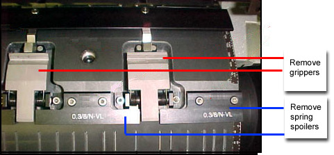
- Undo the screws of each spring spoiler and then remove all the spoilers.
- Undo the screws on each head gripper and then remove all the head
grippers:
-
Use a cloth dipped in alcohol to clean the area of the drum where
the holes will be drilled.
- Cover the drum and fiber head with a nylon sheet. Attach the sheet
to the drum with masking tape:
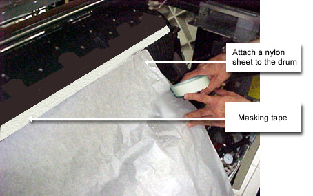
During the drilling process, the sheet will help to protect the drum
from debris such as silicon remnants and Loctite.
- Position the align jig (p/n 252-03158A) on the drum. Align the
two holes on the jig with the holes where the spring spoiler and align
pin were positioned:
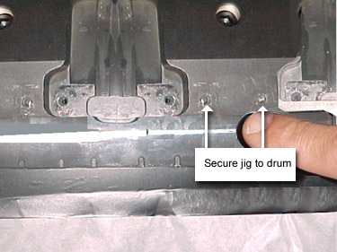
Secure the align jig to the drum with two screws and a hex #8.
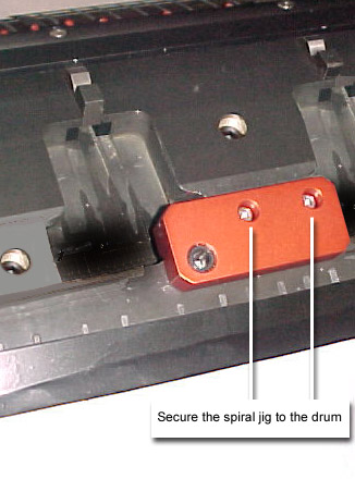
- Position the spiral jig (p/n 252-03157A or 252-03156A) on the
drum. Align the two holes on the jig with the holes where the spring
spoiler and spiral pin were positioned.
Note: The two spiral jigs slightly differ in appearance.
Jig p/n 252–03157A has a distance of 20.7 mm from the
drilling hole to the nearest screw hole, whereas jig p/n 252-03156A
has a distance of 22.7 mm from hole to hole. Use the jig that is
most appropriate to the customers' spiral punch configuration.
Secure the spiral jig to the drum with two screws and a hex #8:
Drilling holes for the new spring spoilers
and pins
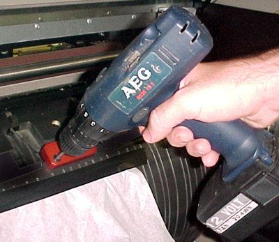
- Connect a 6 mm drill bit (p/n 690-00127A) to a drill.
- Insert the drill bit into the hole on the align jig and then drill
a 1.5 mm deep hole into the drum.
Tip: Always hold the drill straight and drill slowly:
- Measure the depth of the hole with a caliper:
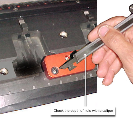
If required, repeat the drilling process, until the hole reaches the
required depth of 1.5 mm.
- Insert the drill bit into the hole on the spiral jig and then drill
a 1.5 mm deep hole into the drum. Check the depth of
the hole with the caliper.
- Remove both the align and spiral jigs.
- Use a cloth dipped in alcohol to clean the area of the drum where
the holes were drilled.
- Remove the nylon sheet and masking tape.
Reassembling the new head grippers,
spring spoilers and align/spiral pins
Note: Use Loctite 242 on all screws and tighten with
a torque meter 20 lb-in
- Reassemble the seven new head grippers
- Assemble all the new spring spoilers, except the two side spoilers
on the drum:
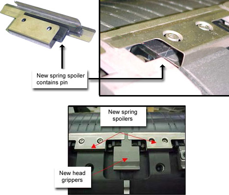
- Press the grippers with your hands to make sure the spring spoilers
can move freely up and down without touching screw heads.
- Assemble the two side head grippers.
- Use philips sunken head screws to install the two levers located on
either ends of the drum:
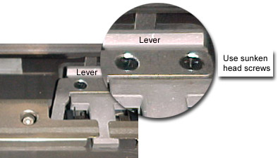
- Use philip screws and nuts to assemble the left and right end spoilers:
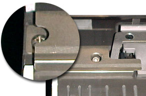
Make sure the levers are capable of lifting the spring spoilers and
that they are not touching the drum surface.
Implementing FCO #27847 - Needle bearing for
gripper actuators
Implement FCO #27847 before continuing to
the testing step.
Testing the procedures
- With the gripper deactivated, try inserting a 0.05 mm shim in between
each of the spring spoilers and the drum:
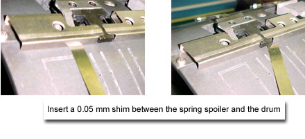
If the shim slides in freely without any resistance, then replace the
spring spoiler because it is slightly bent.
- Test the right and left grippers by trying to insert a 0.05 mm shim
in between the drum and the two sides of the gripper:
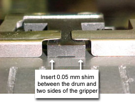
If the shim slides in freely without any resistance, then use the
jig to adjust the gripper lever.
- Remove the lever from the drum and install it onto the jig. Make sure
the screws are tightened:
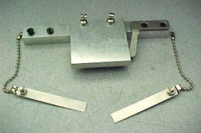
- Try to insert the 0.05 mm shim in between the lever and the jig:
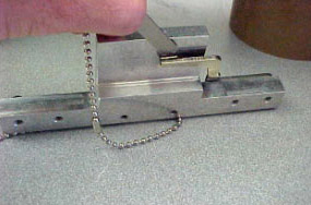
If there is resistance to the shim or it is not entering at all,
then remove the lever from the jig and place it in a fixed vice. Tap
slightly on the lever to reduce the angle of the lever. Reassemble
the lever on the jig and check once again for resistance.
Repeat this procedure until the 0.05 mm shim can move between the
lever and the jig without any resistance.
- Repeat the above procedure with a 1 mm shim. If the 1 mm shim can
move without any resistance between the lever and the jig, then remove
the lever and place it in a fixed vice. Tap slightly on the lever to
enlarge the angle of the lever.
- Reassemble the lever back onto the drum.
- Place the head grippers under the unload gripper actuator.
- Activate the gripper actuator via Lotem Controller. Check that the
head gripper correctly opens.
- Repeat the test with the load gripper actuator.
- Make sure that the indent located on the plate is adjusted in accordance
to the spiral pin on the drum. Adjust if necessary.
- Load plates ranging in size from 0.15 - 0.3 mm. Make sure that the
plates are attached to the pins on the drum. If they are not, make an
adjustment.
- Load a full format plate and check the attachment at the edge of the
plate close to the head grippers.
Note: To check the pin attachment, look at the plate
from straight on and not from above as was the case with the old spoilers.
|

