Home | Contact Us | Submit Troubleshooting Info | Search | Help


    Output | Software Solutions | Proofing | Color, Screening and Calibration | Scanning | Digital Photography | Consumables | POS


Lotem 800 V/VL

FCO 27847 - Needle bearing for gripper actuators

Description: To improve the gripper actuators reliability.
If you are working on the Lotem 800 V, this FCO must be implemented in conjunction with FCO27648 - Spring spoilers update #1.
If you are working on the Lotem 800 VL, this FCO must be implemented in conjunction with FCO #512-02638 - Repositioning the align/spiral pins on the Lotem VL

Prepared By: Itai Peperovich

FCO Kit No: 510F27847

Comp. Level:

Machine S/N:

Catalog No: 507F1L024

S/W Affected:

Type of Change: Conditional

Total Number of Pages:

Product Mgr: Nir Halup

Approval Date:

Product Support: Itai Peperovich

Approval Date: 12-Sep-2001

Customer Support Mgr: Assaf Zach

Approval Date:

1. Reason For Change

  1. To replace the actuators pin's bronze bearings with needle bearings. This will increase the extending life of the actuators.
  2. To replace the bronze fixed and adjustable wheels (if they exist) on both gripper actuators with ball bearing wheels, in order to improve grippers reliability when working with spring spoilers.

2. Description of Change

  1. Change all the bronze bearings with needle and ball bearings.
  2. Replace the gripper's pin actuators.

3. Change Procedure

  1. From the GUI, open the front and rear doors.
  2. Open the side doors and remove the upper back panel.
  3. Disconnect the air pressure supply to the machine.
  4. Shut down the application and turn off the machine main power supply.
  5. Disassemble the upper grippers assembly, use the procedure in the Tic: drum3.htm
  6. Place the upper gripper assembly on a working table.
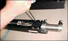
  7. Remove the fixed and adjustable bronze wheel supports with a Philips screwdriver (see picture no. 1).

    Note: If the wheel supports was already replaced to the ball bearing, remove only the fix wheel.

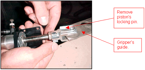
  8. Remove the piston bracket (see picture no. 2).
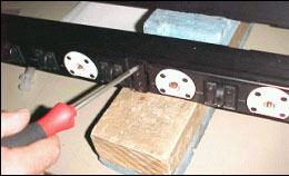
 
Picture no. 1
 
Picture no. 2
  1. Pull up the piston with the gripper guide. Disconnect the piston by removing the locking pin (see picture no. 3).
Picture no. 3
 
  1. Disassemble the actuator pins from the gripper guide. Clean the guide with a piece of cloth and alcohol.
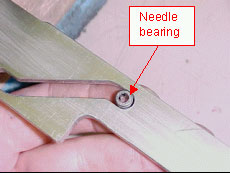
  2. Insert a needle bearing into the gripper guide slot (see picture no. 4).
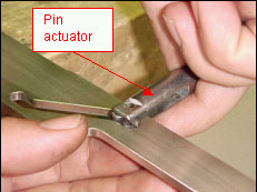
  3. Install a new actuator pin into the guide. Make sure the needle bearing is inside (see picture no. 5).
   
   
Picture no. 4
 
Picture no. 5
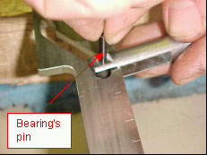
  1. Insert the bearing's pin through the actuator pin and the needle bearing (see picture no. 6).
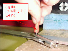
  2. Flip over the gripper actuator and install the locking E-ring on the bearing pin using the special jig supplied with the FCO kit (see picture no. 7).

    Note: Make sure the E-ring sits correctly in its slot.
  3. Repeat step 11 to 14 for all the actuator pins.
   
   
Picture no. 6
 
Picture no. 7
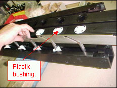
  1. Re-install the gripper guide with the new actuator pins into the gripper assembly. In the old gripper assemblies, the bronze bushings must be slightly greased. The new ones are made of plastic, and grease is not needed (see picture no. 8).
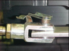
  2. Re-connect the piston to the gripper guide. Secure it with the clamp pin (see picture no. 9).
   
   
Picture no. 8
 
Picture no. 9
  1. Re-assemble the piston's base to the gripper assembly. Apply loctite 242 and tighten the four screws (see picture no. 2).
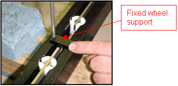
  2. Re-Install the fixed guide supports. Apply loctite 242 on the screws (see picture no.10).

    Note: The adjustable wheel supports should always face the drum.
    Picture no. 10
     

  3. Re-assemble the upper gripper actuator according to the procedure in the TIC.
  4. Disassemble the lower grippers actuato.
  5. Repeat steps 7 to 20 on the lower gripper actuator assembly.
  6. After installing the lower and upper grippers actuators make sure that:
    • The H.P and E.P detectors are connected.
    • Air supply hoses are connected to the pistons.

4.Test Procedure

  1. Reconnect the air pressure supply.
  2. Reconnect the power supply and power up the machine and application.
  3. From the GUI, open the following dialogs:
    • Drum motor.
    • Load and unload gripper valves.
    • Load and unload H.P and E.P detectors.
  4. Send the drum to position of the load gripper location, you can find the parameter in the Registry: Loading System\setup "Load head gripper location".
  5. After the drum reaches this position, activate the load gripper valve and check for smooth operation, if needed adjust the speed of the piston using the air valve regulators.
  6. Check that the flag (gripper guide) is activating the End position detector and Home Position detector.
  7. Send the drum to position of the load gripper location, you can find the parameter in the Registry: Loading System "Unload head gripper position".
  8. After the drum reach this position, activate the unload gripper valve and check for smooth operation, if needed adjust the speed of the piston using the air valve regulators.
  9. Check that the flag (gripper guide) is activating the End position detector and Home Position detector.
  10. Perform loading and exposure sequence to verify that all the loading and unloading sequences work correctly.

5. Parts List

PART

QTY

DESCRIPTION

290A6B840 18 GRIPPER PUSH ROD PIN II
290A6B890 20 PIN-1
290B7B089 1 GRIPPER ACTUATOR RET. RING JIG
359B50000 20 SHELL BEARING ID=. 125" OD=. 25"
363G03100 44 RET.RING, EXT.BER.COP.ID=. 112"
374A00080 1 PACKING LABEL-WHT
380G03041 16 PHIL FLAT HD STST 6-32*3/8"
507A3D838 4 ADJUSTABLE WHEEL ASSY
507A3D839 4 FIXED WHEEL ASSY
480C10192 1 ADH.RET.10CC LOCTITE 242
719-00197A 1 NEEDLE BEARING FOR GRIPPER ACTUATOR-27847

6. Attached Documentation

None.

7. Material Disposition

Dispose off the old parts.

8. Logistics

8.1 Approved quantities:

CSA

:

40

CSE

:

40

CSAP

:

5

CSN

:

5

CSMA

:

5

Other :  
No Limit :  

8.2 Schedule supplies for first lots:

D.U

Month

QTY

Month

QTY

Month

QTY

CSA

:

October 20 November 20    

CSE

:

October 20 November 20    

CSAP

:

October 5        

CSN

:

October 5        

CSMA

:

October 5        

Other

:


8.3 Inventory in warehouses:
None.


Rev A


    Copyright © 2005 Creo Inc. All rights reserved. Confidential. Back to top.