

Home | Contact Us | Submit Troubleshooting Info | Search | Help
Output | Software Solutions | Proofing | Color, Screening and Calibration | Scanning | Digital Photography | Consumables | POS
Home | Contact Us | Submit Troubleshooting Info | Search | Help
Output | Software Solutions | Proofing | Color, Screening and Calibration | Scanning | Digital Photography | Consumables | POS
| Lotem 800 Installation Guide Hardware Installation |
Opening Doors and
Removing Securing Ties
Optomechanic to Chassis Locking Devices
Carriage to Optomech Locking Devices
The platesetter is shipped with several safeguards that prevent excessive movement of internal parts during transport.
Opening Doors and Removing Securing Ties
To access the securing ties, you need to manually open the Upper front and rear doors.
Optomechanic to Chassis Locking Devices
The special locking devices secure the Optomechanic assembly to the main frame during transport. There are four such locking devices - two on the front side of the platesetter, and two on the rear side. The locking devices are red for easy identification. Figure 2-7 and Figure 2-8 show the locking devices and their locations.
Carriage to Optomech Locking Devices
Two locking devices secure the carriage to the V block during transport. There are two such locking devices - one in front of the carriage and one behind the carriage. Both are accessed from the rear side of the platesetter. See Figure 2-9.
Note: After removing the locking devices, visually inspect the components inside the machine to verify that they are undamaged.
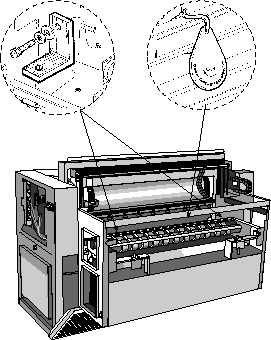
Figure 2-7: Optomechanic to Chassis locking devices, platesetter front view
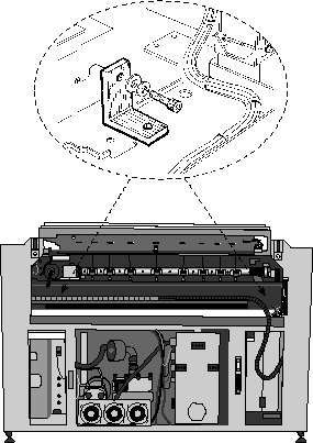
Figure 2-8: Optomechanic to Chassis locking devices, platesetter rear view
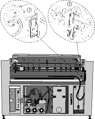
1 - front carriage to guide beam locking device
2 - rear carriage to optomech locking device
Figure 2-9: Carriage to optomech plates, platesetter rear view
Copyright (c)1998 Scitex Corporation Ltd. All rights reserved. Certain names, logos, designs, titles, words or phrases on this page may constitute trademarks, servicemarks, or tradenames of CreoScitex Corporation Ltd. or other entities which may be registered in certain jurisdictions.