The objective of the evaluation test is to find the
optimal elevation angle of the optical head. A test file is exposed in resolution 100. If
an elevation problem is detected in the exposed file, the elevation mechanism is adjusted
until the results are satisfactory. The test results do not depend on plate type, size or
thickness, therefore it can be performed on any plate the customer uses.
Select the laser group that will be exposed, as follows:
Right click on the mouse to select to open the Laser
group menu.
On the menu, double click on Last laser active.
Change the last beam from 23 to 3 and press Enter.
Press Send and then Save (only the first 4
beams will be exposed).
Choose Focus from the Calibration type menu.
The Lotem calibration window for the Focus test opens (see "Focus test").
Choose the optical focus value that you found in the focus
test.
Reduce the Intensity by 40%.
For Number of Steps enter 11.
Expose the test file (the first 4 beams will be
exposed).
Right click on the mouse to select to open the Laser
group menu:
Double click on Last laser active.
Change the last beam to 23.
Double click on First laser active.
Change the first beam to 20.
Press Send and then Save (only the last 4
beams will be exposed).
Repeat steps 2 to 5. When setting the Expose
parameters, enter an offset value - enter an offset value aroundthe drum
so that the batch of strips will be below the first set of strips.
To determine if the elevation of the optical head is
correct, you need to examine the results of the two sets of exposed strips:
Determine the best focus value in each set of strips.
If the best focus value is identical in both sets,
this implies that the elevation is correctly adjusted.
If the best focus value is not identical in both
sets, this implies that the elevation requires adjustment. Proceed to Elevation
adjustment.
Elevation adjustment:
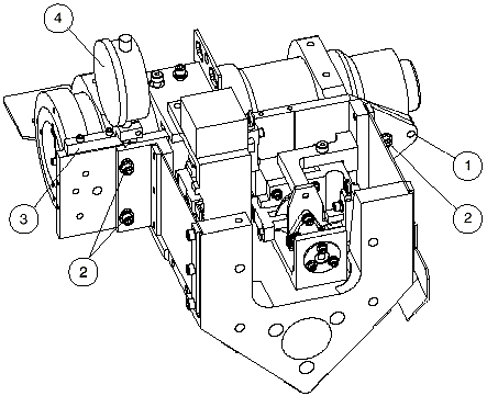
The following explains how to adjust the optical head
elevation (the numbers in brackets identify the parts shown in Figure
5-2).
Connect an elevation jig [3] to the optical head.
Connect a dial indicator [4] to the elevation jig.
Open the three screws [2] of the optical head; open the
screws until the point of friction, that is, open until the friction is strong enough to
hold the optical head but still enable adjustment.
Change the elevation angle of the optical head by rotating
around the pin [1] and moving the optical head 0.2 mm upwards. Watch the dial indicator as
you move the optical head.
Close the three screws [2].
Repeat the test - expose the test file and examine the
results.
If the test results are satisfactory, the elevation test is
completed.
If the test results are better than the previous results,
but still not satisfactory, readjust the elevation by further moving the optical head in
the same direction.
If the test results are worse than the previous results,
readjust the elevation by moving the optical head in the opposite direction.
The test should be repeated until the elevation results are
satisfactory.
Secure each screw, one by one, using "Locktite"
(make sure not to change the adjustment).
Figure 5-2: Carriage including optical head
Copyright
(c)1998 Scitex Corporation Ltd. All rights reserved. Certain names, logos,
designs, titles, words or phrases on this page may constitute trademarks, servicemarks,
or tradenames of CreoScitex Corporation Ltd. or other entities which may be
registered in certain jurisdictions.