Background |
|
The objective of the elevation test is to find the correct elevation
angle of the optical head. When the elevation angle is correct, all 24
or 48 beams along the V groove are in focus. Incorrect elevation results
in a different optimal focus value for beams from one side of the V groove
to the other. Incorrect elevation can cause an image shift of about 1
mm around the drum and banding, as well as uneven density within the 24/48-beam
swath. Correct elevation is pre-set at the factory and rarely needs to
be adjusted. Plate fly-off or other physical damage to the otpic tube
may disrupt the elevation angle, requiring it to be readjusted.
Elevation does not depend on plate type, size or thickness. The test
and adjustment (if needed) can be performed on any plate the customer
uses.
|
Procedure |
|
This procedure includes the following:
Elevation Test
Two focus tests are exposed on the same plate. The first focus test uses
only the first five beams while the second test uses only the last five
beams. If the elevation angle is correct, the optimal focus value will
be the same (+/- 10 microns) for both tests.
- Focus tests are best run with reduced
intensity.
- To find the best intensity for this test with a particular plate
emulsion, find the intensity threshold, as follows:
- Using an intensity range between 0 and the default value,
run an intensity test.
- Unload the plate.
- Find the minimum intensity that exposes the plate, then select
an intensity one or two steps higher for running the Focus tests.
Right-click Utilities/Hardware/Expose System/Laser System/Laser
Group to open the Properties dialog box.
Change Last_Expose_Laser_Active to 4.
From the Brisque, run the first focus series at res 100
and at the same time, instruct the Brisque not to unload
the plate.
Return the Last_Expose_Laser_Active to its original
value; then set the first expose laser active, as follows:
- For a 24-beam machine, change the First_Expose_Laser_Active to
19.
Or
- For a 48-beam machine, change the First_Expose_Laser_Active to 43.
- Offset the image around the drum by 250 mm.
- From the Brisque, run the second focus series at res 100.
Make sure to use the same range and increments as before.
- Process the plate. If the elevation is correct, the best focus value
for both series will be the same. If the best focus value is more than
a 10-micron difference between the two tests, follow the adjustment
procedure below.
- Remember to re-enable all lasers in the Lotem.
Adjustment
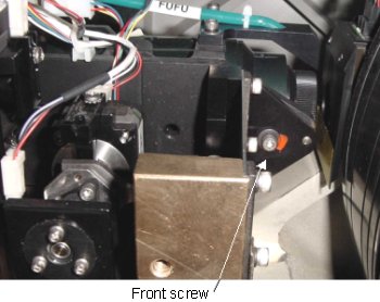
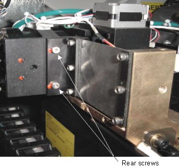
- Loosen all three of the telescope screws
(front and rear screws), as shown below. Make sure to loosen the rear
silver screws, and not the small black set screws.
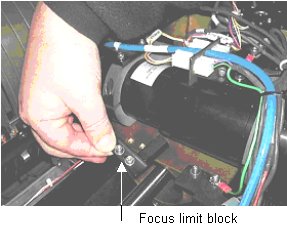
- Remove the focus limit block on the carriage.
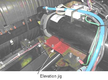
- On the left side of the carriage (from where you just removed
the focus limit block), insert the elevation jig under the telescope
tube. Make sure the telescope and the surface of the jig are evenly
aligned and fit snuggly together.
- Tighten the three screws that were loosened in step one.
Note: The two screws in the jig limit how far the jig
goes under the telescope.
- Remove the jig and reinstall the focus limit block.
- Move the Focus motor to the home position (HP).
- Using the tombstone jig, check the lens and drum clearance.
Note: If you do not have a tombstone jig, the clearance
should be 11.5 mm from the drum to the lens protector.
- Perform the Focus motor procedure
as a check to ensure that moving the focus motor to its maximum distance
will not put the optics on a collision path with the grippers.
- Run the elevation test. If adjustment
is needed, calculate the amount of adjustment required, as follows:
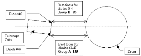
Use groups of 5 diodes, as indicated in the following
examples:
- Diodes 43-47 (20-24) Group A, have a best focus value of 135.
- Diodes 0-4 Group B, have a best focus value of 95.
- To calculate how much to change
the elevation, subtract the best focus value for diodes 43-47 Group
A from the best focus value for diodes 0-4, Group B; then divide the
result by 2. If the result is negative, you need to lower the rear of
the telescope tube by that many microns. If the result is positive,
you need to raise the back of the telescope tube by that many microns.
When B-A=C and C is a negative value, you
need to lower the back of the telescope tube. When B-A=C and C is a positive
value, you should raise the back of the telescope tube.
To reiterate: If A is greater than B, lower
the rear of the tube. If A is less than B, raise the rear of the tube.
- Install the elevation measuring jig on the back of the
telescope tube, as shown below.
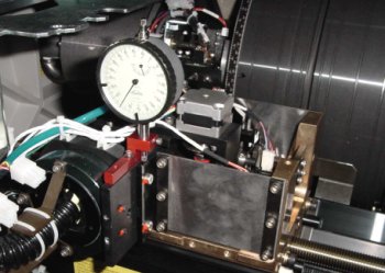
- Set the dial indicator to a known zero position.
Note: Do not loosen the front screw again during the
procedure. (When the front screw is loosened again, the front of the
telescope drops down and upsets the adjustment.)
- Adjust the telescope tube position by the amount calculated in step
10. When you have made the adjustment, tighten the two rear screws
and then remove the elevation measuring jig.
- Run another elevation series, as described
above to confirm the result.
- When you are satisfied with the elevation result, re-enable all the
lasers.
|

