Procedure |
|
This procedure consists of the three steps:
Removing the existing V-block
- From the hardware tree, send the carriage to absolute position 1150.
(Hardware/Expose System/Carriage System /Carriage Motor).
- Open the top rear cover.
- Remove the upper rear panel.
- Shut down the platesetter via the main power switch.
- Remove the unloading tray.
- From the right side of the platesetter, remove the right local board—located
close to the carriage motor.
Note: If the Lotem 800
platesetter is a Local2 device, remove the local board on the left side
in addition to the local board on the right side.
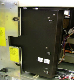
- From the left side of the platesetter remove the oil bracket.
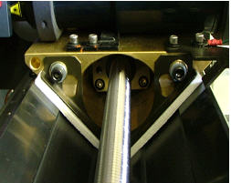
- Remove the three screws securing the leadscrew coupling.
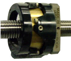
- From the right side of the platesetter, disconnect the stepper motor
connector, and the coarse and fine home position detectors.
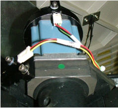
- Remove the four screws securing the bearing house to the V-block.
Make sure you also remove the grounding wire and the Molex connector—both
of which are secured with screws.
- Extract the leadscrew and the attached motor. Be careful not to damage
the leadscrew or leadscrew threads.
- Secure the alignment jig (290B8L013) to the carriage.
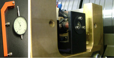
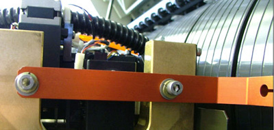
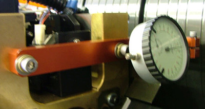
- Manually slide the carriage to the left side of the V-block.
- Use the alignment jig to record the distance
between the carriage and the drum surface.
- Remove the two screws securing the L-box, and then open the
L-box.
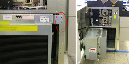
- Carefully extract the carriage and the attached jig from the V-block.
Note: Do not remove the
jig.
- Use a 39 nm (350 lb/in) torque to remove the four screws from the
underside of the platesetter. Note that there are two screws on the
left underside and two screws on the right underside.
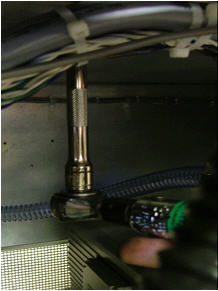
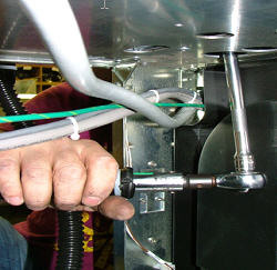
- Remove the V-block from the platesetter.
Assembling the replacement V-block
- Use alcohol to clean the underside of the replacement V-block.
- Install the replacement V-block onto the drum chassis.
- Insert, but do not tighten, the four V-block screws.
- Install the carriage, but not the leadscrew, onto the V-block.
- Manually slide the carriage to the position recorded with the alignment
jig - see step 14.
- Use the alignment jig to record the distance between the carriage
and the drum surface. If required adjust the V-block until the distance
is equal to the distance recorded in step 14.
- Manually slide the carriage to the right side of the V-block, and
record the distance between the carriage and the drum surface. If the
difference between the two recorded measurements is greater than 5 microns,
adjust the V-block until it is parallel along its entire length with
the drum surface.
- When the V-block is parallel to the drum, use the 39 nm (350 lb/in)
torque to tighten the four V-block screws.
- Verify that the carriage is still parallel to the drum surface
(±5 microns). If required, release the V-block screws and repeat
steps 7 to 9 inclusive.
- Remove the alignment jig from the carriage.
- Insert the coupling locator jig (291A3L006) through the lower hole
on the coupling.
- Insert the coupling into the carriage.
- Use the coupling locator jig to align the hole on the carriage to
the hole on the coupling.
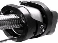
- Insert, but do not tighten, the upper two coupling screws.
- Remove the coupling locator jig and insert the third screw into the
coupling.
- Tighten all three coupling screws.
- Reinstall the four screws securing the bearing house to the
V-block. Make sure you also reinstall the grounding wire and the Molex
connector.
- From the right side of the platesetter, reconnect the stepper motor
connector, and the coarse and fine home position detectors.
- Use silicon oil to lubricate the inner surface of the V-block and
oil bracket.
- From the right side of the platesetter, reinstall the right local
board. If the Lotem 800 platesetter is a Local2 device, also reinstall
the local board on the left side.
- Reinstall the unloading tray.
- Reinstall the upper rear panel.
- Close any open doors and covers.
- From the main power switch, reconnect the power to the platesetter.
- From Lotem Controller, send the carriage to home position and end
position. This ensures that the V-block is well lubricated.
Calibrating the Lotem 800 platesetter
Calibrate the Lotem 800 platesetter as described in the Lotem
800 Calibration procedure.
|