Background |
|
The edge detection calibration procedure, starting from version 3.61.00/1.60.09,
has been automated and simplified. This procedure replaces all previous
procedures and updates, and should be implemented on all versions prior
to version 3.61.00/1.60.09.
Edge detection enables accurate image positioning on the plate. Each
time an exposure sequence begins, a single laser diode is activated (normally
diode 0) and it emits a beam which is directed onto the drum. The reflection
from the beam is detected by an extra optical fiber, adjacent to fiber
#0 located in the V groove. The intensity of the reflection is converted
into a measurable voltage by the Slave Sproc situated on the MCF board.
When the beam focuses on a plate, no reflection is detected that can be
translated to a voltage of 0 on the MCF board. When the beam hits the
drum instead of the plate, it is out of focus but still produces some
reflection. This reflection translates to approximately half a volt on
the MCF board. When the carriage moves away from its home position and
the laser beam hits the plate, the voltage changes from approximately
half a volt to 0, enabling the edge of the plate to be detected.
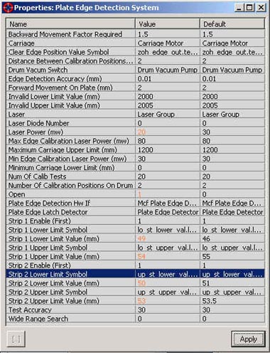
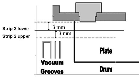
Edge detection takes place along a very narrow window around the drum,
known as strip 2. It is situated between the end of the
head grippers and the beginning of the vacuum grooves. This is because
the reflection from the grippers or vacuum grooves may be similar to the
reflection from the plate.
Upon completion of this procedure, the field service engineer will have
modified the following three calibration parameters:
- Min Edge Calibration Laser Power (mw): Power required
from the single laser beam during edge detection.
- Strip 2 Lower Limit Value (mm):
The beginning location around the drum for edge detection
- Strip 2 Upper Limit Value (mm): The end location
around the drum for edge detection
Note: The difference between these two values should
be 3 mm.
- Strip 1 Lower
- Strip 2 Upper
|
Procedure |
|
This procedure includes the following stages:
Preparation
Note: Before you start the edge detection procedure, ensure that
the optics for the plate thickness being used are in correct focus.
Before you start the focus calibration, disable the edge detection: Expose
> Plate Edge Detection Enable = 0
After finding the correct focus value, re-enable the edge detection: Expose
> Plate Edge Detection Enable = 1
- Clean the lens, and perform a focus test.
Make a note of the correct focus value for this plate. You will need
to use this value later in the procedure.
- Load a new plate on the drum. If possible, use a medium or small size
plate. Load the plate so that the outermost vacuum groove is still visible.
If necessary, load the plate off center.
- Close all the platesetter's covers.
- In Lotem Controller, open the following windows:
| Window |
Path |
| Drum Motor |
Hardware/Drum System/Drum Motor |
| Carriage Motor |
Hardware/Expose System/Carriage System/Carriage Motor
|
| Focus Motor |
Hardware/Expose System/Focus System/Focus Motor |
| Laser Group |
Hardware/Expose System/Laser System/Laser Group |
| Slave Sproc under MCF |
Hardware/Boards/MCF Boards/Slave Sproc |
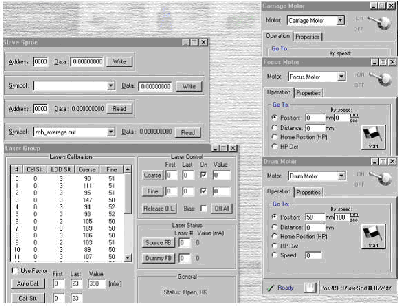
- To easily view the information in the windows, arrange them
as shown:
Defining the upper and lower limits
for strip 2
Use the laser to draw a line across the plate within the range of edge
detection.
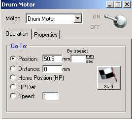
- Send the drum motor to position 50.5 mm:
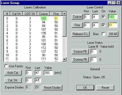
- In the Laser Group window, enter a value of 300 mw;
then click Auto Cal.
- Copy the Coarse and Fine values
for beam 0 to the Laser Control area:
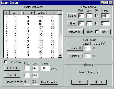
In order to draw the line across the plate using five beams, set the
First beam to 0 and the Last
beam to 4:
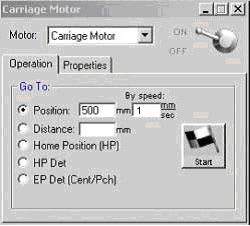
- Send the carriage motor to a position approximately 20 mm
from the edge of the plate. Use the fast (default) speed value.
- In the Laser Group window under Laser Control, select
the On checkbox for both Coarse and Fine.
- Click the Coarse and Fine buttons. This will activate
the lasers.
- To draw the line across the plate, send the carriage to Position
500 mm at a slow speed of 1 mm/sec:
- Return the carriage motor to a position approximately 20 mm
from the edge of the plate.
- Press the Off All button to close all the diodes.
Note: Do not move the carriage to home position when
the lasers are on and do not remove the plate from the drum.
- Open the rear door and examine the line. Note that on most plates
the line will be visible without developing the plate. In addition the
different drum speeds affect the characteristics of the line:
- On a Lotem 800, running at 900 rpm, the line should be 3 mm when
measured from the edge of the head grippers to the laser line.
- On a Lotem 400, running at 1200 rpm, the line should be 4.2 mm
from the edge of the head grippers.
If the line is not the required length for the appropriate speed,
then redraw the line, changing the drum motor position
slightly until it is the required distance from the edge of the head
grippers. Mark the motor position as Strip 2 Lower.
- Calculate Strip 2 Upper as follows:
Strip 2 Upper = Strip 2 Lower + 3 mm (depending
on drum speed)
- Close the rear door.
- Enter the lower and upper limit values that you took for Strip 2:
Defining the upper and lower limits for strip 1
strip 1 lower = strip 2 lower - 1
strip 1 upper = strip 2 upper + 1
Defining the minimum laser power required for
edge detection
- Open the Plate Edge Detection window:
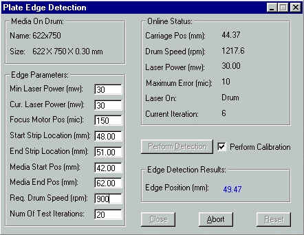
- Change the values in the Req. Drum Speed (rpm)
according to the Lotem:
Lotem 400 - 1200 rpm
Lotem 800 - 900 rpm
- In the Plate Edge Detection window, select the Perform Calibration
checkbox.
The platesetter automatically finds the best laser power (20 tests),
and updates the Min Edge Calibration Laser Power (mW)
value in the registry.
- To perform edge detection on plate, do the following:
- In the Plate Edge Detection window, clear the Perform
Calibration checkbox.
- In the Num of Test Iterations textbox, enter
50.
- Press the Perform Detection button.
The platesetter performs 50 edge detection tests. If the task fails,
an error message appears on the screen. When this occurs, clean
the drum at the edge position or change the strip's lower/upper
limit value.
- In the Last Detected Position area, the position number changes
each time the carriage position stops. As the plate edge is detected,
the number will momentarily flicker. Write this number down for each
repetition of the test. If the edge detection is working accurately
the detected edge will not vary more than +/- 0.01 mm from the
end position.
If the variance exceeds +/- 0.01 mm, increase the laser power by
5 mW; then repeat the test. Make sure to change the Min Edge Calibration
Laser Power (mW) parameter accordingly, if this works.
Checking the MCF signal in a stationary position
- Makes sure the focus is correct.
- Perform drum init.
- Perform an edge detection test so that the Sproc can be loaded.
Note: There is a high probability that the test will
fail.
- Send the carriage to the Height Start Image Area (mm)
position.
- Send the drum to the Strip 2 Lower Limit Position.
- Activate the '0' (zero) diode according to the following parameters:
Coarse = 8, Fine = 51
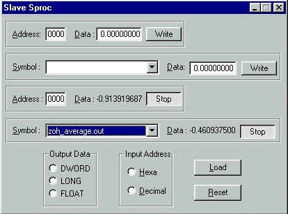
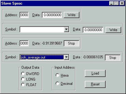
- Within the application, open the Slave Sproc window:
Boards/mcf boards/ Slave sproc.
- In the lower Symbol box, select Zoh_average.out and
then select Read, which will appear where the Stop
is currently located.
Note: When the laser is pointing at the drum, it
should be stable and the expected voltage should be approximately
0.5V.
When the laser is pointing at the plate, it should be stable and the
expected voltage should be 0.0V.
|

