Requirements
|
|
| Description |
Qty |
Part Number |
| MCF Board |
1 |
503C2L166P |
| Edge Detection Board |
1 |
505B2D349 |
| Edge Cable, L-Box to E-Box L=4.25 |
1 |
504L2D386 |
| Right Alignment Pin for Half-Web |
1 |
290B6B195 |
| Alignment Pin II for Quantum |
1 |
290B7B120A |
| Flt. Wash. 0.17x5/16x.065 St. Cad |
4 |
382A10004 |
| Spring Spoiler 160 mm |
1 |
291A2U030 |
| Spring Spoiler 100 mm |
1 |
290A2U028 |
| |
|
|
| Optional kits needed for Lotem 800 FH platesetter |
| Description |
Part Number |
| Lotem 800, punch conflict location 476 mm |
518-00300A |
| Lotem 800, punch conflict location 411 mm |
518-00301A |
| Lotem 800, punch conflict location 381 mm |
518-00302A |
| Lotem 800, punch conflict location 276 mm |
518-00303A |
|
Procedure
|
|
To implement a field upgrade:
- From the application, open the front door.
- Close the application, and shut down the platesetter.
- Open the left hand side Lotem door.
- Open the L-Box door and check whether the edge detection board is
installed. If it is, make sure the power cable and the two orange fiber
optics are connected.
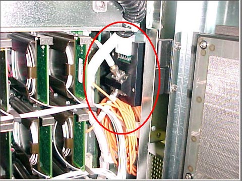
- If the board is not installed, order the board (edge detection
board p/n: 505B2D349) and install it.
- Connect the power cable and two orange fiber optics
to the edge detection board.
- Check whether the edge cable, leading from the L-Box to the E-Box
is already installed. If it isn't, order the cable (p/n 504L2D386) and
connect it, as follows:
- E-Box: 15-pin connector
- L-Box: 9-pin connector
- Close both the L-Box and left hand side Lotem doors.
- Close the front Lotem door.
- Power up the platesetter, and start the application.
- Back up the platesetter registry, database and DDB parameters.
- Install version 3.61.02, according to the Release
Notes.
- Make sure the platesetter is in Ready mode; then
load the application.
- In the registry, change the following parameters:
- Expose\Plate Edge Detection Enable=1
- IO OBJECTS\Mcf Plate Edge Detection HwIf=1
- IO OBJECTS\Mcf Plate Edge Detection HwIf\Edge Threshold Value=-0.25
- IO OBJECTS\Mcf Plate Edge Detection HwIf\Edge Voltage Reference
Value=-0.1
- IO OBJECTS\Plate Edge Detection System=1
- IO OBJECTS\MCF CARDS\MCF CARD\LATCH DETECTORS\Plate Edge Detector=1
- Machine\Plate On Drum Height Axis Absolute Position Error (mm)=20
- Select the largest plate; then change its positioning from
Spiral Punch to Edge, as follows:
- Change to Expert mode by pressing Ctrl-u.
- Click the Media Definitions button.
- Select the largest plate size.
- Press the Adv. button.
- Change the Positioning Type from Spiral Punch to Edge.
- Press Save, and close the dialog.
- From the Loading System dialog, load the plate on the drum.
- Following the Edge
detection calibration procedure, find and update the following parameters
in the machine's registry:
- IO OBJECTS\Plate Edge Detection System\Strip 2 Lower Limit
Value (mm)
- IO OBJECTS\Plate Edge Detection System\Strip 2 Upper
Limit Value (mm)
- IO OBJECTS\Plate Edge Detection System\Min Edge Calibration
Laser Power (mw)
- After confirming that the edge detection is working properly, start
the hardware implementation:
- Unload the plate.
- Disassemble the head spoilers and registration pins (regular
and GTO, where applicable).
- If there is no clearance for the new registration pins, use the
appropriate drilling jig to make the clearance.
- Using the special flat washers (p/n 382A10004), install
the registration pins and head spoilers.
- Disconnect the punch cables.
- If both the regular spiral punch and the GTO spiral punch are
installed, remove them.
- Close the following parameters in the registry:
- EXPOSE\Spiral Punch Motor Enable=0
- IO OBJECTS\PUNCH SYSTEM\Punch System\Punch Spiral Unit=NONE
- IO OBJECTS\PUNCH SYSTEM\Punch System\ Secondary Punch Unit=NONE
- IO OBJECTS\LOCAL 3\PUNCH MOTORS\Punch Motor #03\Open=0
- IO OBJECTS\LOCAL 3\DETECTORS\Punch Motor #3 Home Pos. Detector\Open=0
Note: If a GTO spiral punch is installed, close its
motor and detector in the registry.
- Close all doors.
- Perform image parallelism calibration on plate. If necessary, adjust
the parallelism by moving registration pins on drum.
- Check edge detection stability and operation consistency.
|

