Procedure |
|
Checking and adjusting the top-rear cover
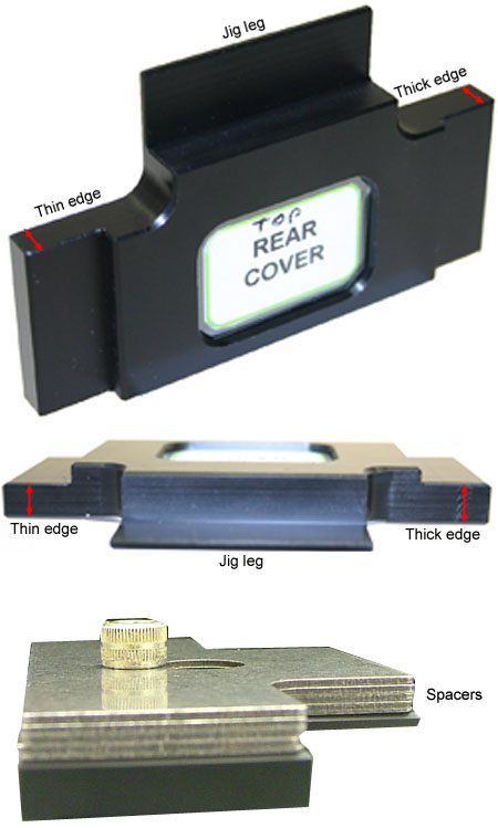
- Remove the T-shaped rear cover jig (part number 690-00721A)
from the Lotem 800 doors and interlocks adjustment jigs kit (part number
518-01578A). The jig comprises of a leg and two protruding edges.
- The leg of the jig is used for determining the correct width of
the groove formed between the top-rear cover and the top-rear panel.
- The thin and thick protruding edges of the jig are used for determining
the correct position of the Omron interlocks:
Click image for detailed
view
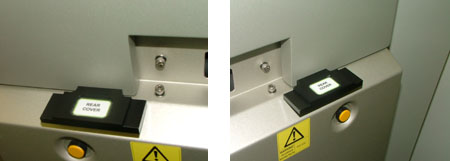
- Insert the leg of the jig into the groove formed between the top-rear
cover and the top-rear panel:
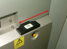
- Slide the jig along the length of the left side groove and then the
right side groove. Make sure that the jig is kept perpendicular to the
grooves at all times:
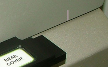
- Use the jig to locate the two points (one per
each side) where the grooves are at their narrowest. Mark these points
with a pencil:
If the leg of the jig cannot fit into the grooves, or if there is no
friction between the jig and the narrowest point of the grooves, adjust
the top-rear cover latches.
- Check the accuracy of the top-rear cover’s
interlocks.
- If required, adjust the interlock operation keys.
- If required, adjust the top-rear cover’s Omron
interlocks.
- Check, and if required, adjust the platesetter’s front cover unload panel and side panel.
Adjusting the top-rear cover latches
- Manually open the top-rear cover.
- Use a 3/8" wrench to release, but not remove, the four screws
securing the latch to the chassis.
- Raise or lower the latch in 1-mm increments:
- If the leg of the jig did not previously fit into the groove,
then raise the height of the latch.
- If the there was previously no friction between the jig and the
narrowest point of the groove, lower the height of the latch.
Important: Ideally,
the groove should be 2 mm wide—which is equal to the width
of jig leg without spacers. However, if the height of the latch
cannot be lowered any further, and there is still too much space
between the narrowest point of the groove and the jig (no friction),
then add either 1
mm spacers (part number 690-00728A, or 0.5
mm spacers (part number 690-00729A) to the jig.
- Close the top-rear cover.
- Slide the jig’s leg along the length of the left side groove:
- Make sure the jig fits into the groove.
- Make sure that there is no excessive friction between the jig
and the groove.
- If required, make further adjustments to the latch’s height.
- Manually open the top-rear cover and retighten the screws securing
the latch to the chassis.
- Repeat steps 2-7 for the right side latch.
- Check the accuracy of the top-rear cover’s
interlocks.
Checking the accuracy of the top-rear cover’s
interlock
- If required, manually open the top-rear cover.
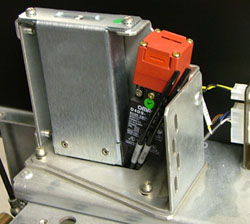
- There are two Omron interlocks located behind the top-rear cover:
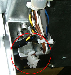
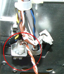
- Disconnect the Molex® connector belonging to the Omron
interlock located on the right side of the top-rear cover:
- Plug the probes into the appropriate jacks on the digital voltmeter:
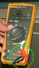
Important: Plug the black
probe into the digital voltmeter’s negative (common) jack, and
plug the red probe into the digital voltmeter’s Volt/ohm/temp jack
(not the A or mA jack).
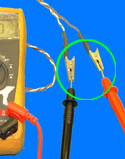
- Remove the interlock jig cable (part number 220-01407A) from the kit.
Located on one end of the interlock jig cable are two crocodile clips,
on the other end there is a Molex connector.
- Connect one crocodile clip to each probe:
- Connect the Molex connector to the interlock’s connector:
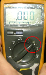
- Set the dial on the digital voltmeter to the diode indicator:
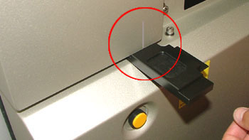
- Insert the top-rear cover jig’s thin edge into the narrowest
point of the right side groove (marked with a pencil):
- Close the top-rear cover.
- The digital voltmeter should make a beeping sound.
If the digital voltmeter fails to beep, adjust the right
side interlock operation key.
- Manually open the top-rear cover and remove the jig.
- Insert the jig’s thick edge into the narrowest point of the right
side groove (marked with a pencil):
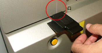
- Close the top-rear cover.
- The digital voltmeter should beep.
If the digital voltmeter does not beep, adjust the
Omron interlock.
- Repeat steps 1-13 on the left side groove and left side interlock.
Adjusting the Omron interlock operation key
- Manually open the top-rear cover.
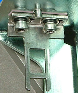
- Use a pencil to mark the outline of the interlock operation key:
- Use a hex key to remove the two screws securing the interlock operation
key.
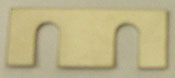
- Add the required number of spacers (part number 252-10209A) to the
interlock operation key assembly:
- Reinstall the interlock operation key, by using the marked outline
as a guide.
- Place two strips of masking tape over each end of the interlock’s
entry point:
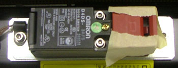
- Close the top-rear cover just enough for the interlock operation key
to punch holes in the masking tape.
- Manually open the top-rear cover:
- If no punched holes appear on the masking tape, then the interlock
operation key is correctly positioned.
- If punched holes appear on the masking tape, reposition the interlock
operation key and repeat steps 6-8.
Adjusting the Omron interlock
- Manually open the top-rear cover.
Important: It is less
time-consuming to remove spacers from the interlock operation key as
opposed to the interlock. Therefore, if possible, try to remove spacers
from the interlock operation key (as described in the section Adjusting
the Omron interlock operation key), before attempting to remove
the spacers from behind the interlock.
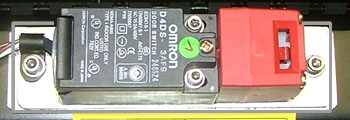
- Before dismantling the interlock, outline its shape with a pencil:
- Use a hex key to remove the two screws securing the interlock.
- Remove the required number of spacers from the interlock assembly.
- Reinstall the interlock by using the marked outline as a guide.
- Place a strip of masking tape over the interlock’s entry point:
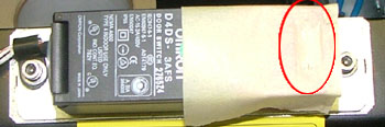
- Close the top-rear cover just enough for the interlock operation key
to punch holes in the masking tape.
- Manually open the top-rear cover:
- If the punched holes appear exactly in the middle of the masking
tape, then the interlock is correctly positioned:
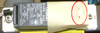
- If the punched holes do not appear exactly in the middle of the
masking tape, reposition the interlock and repeat steps 6-7.
|