Procedure |
|
Checking and adjusting the unload panel
- Make sure the platesetter’s distribution panel is installed.
- Raise the top rear cover.
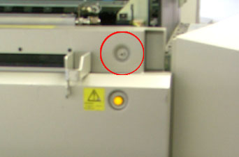
- Remove the black upper screw from the left side of the unload panel:
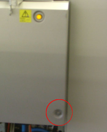
- Release, but do not remove, the lower screw from the left side of
the unload panel:
- Open the left side door and the laser barrier.
- Remove the unload panel jig (part number 690-00723A) from the Lotem
800 doors and interlocks adjustment jigs kit (part number 518-01578A).
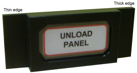
The jig comprises of two protruding edges.
- The thin and thick protruding edges of the jig are used for determining
the correct position of the Omron interlocks:
Click image for detailed
view
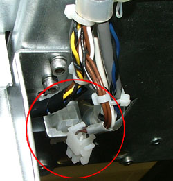
- Disconnect the Molex® connector belonging to the Omron
interlock (located on the left side of the unload panel):
- Plug the probes into the appropriate jacks on the digital voltmeter:
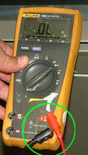
Important: Plug the black
probe into the digital voltmeter’s negative (common) jack, and
plug the red probe into the digital voltmeter’s Volt/ohm/temp jack
(not the A or mA jack).
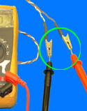
- Remove the interlock jig cable (part number 220-01407A) from the kit.
On one end of the interlock jig cable are two crocodile clips, on the
other end there is a Molex connector.
- Connect one crocodile clip to each probe:
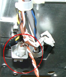
- Connect the Molex connector to the interlock’s connector:
- Set the dial on the digital voltmeter to the diode indicator:
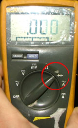
- From the left side door, insert the unload panel jig’s thin edge
between the unload panel and the chassis. For best results, insert the
jig just above the interlock:
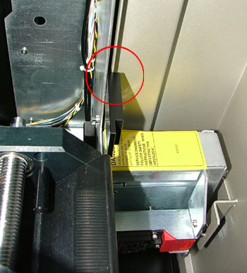
- Push the unload panel against the thin edge of the jig:
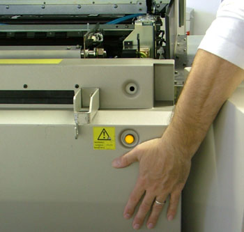
- The digital voltmeter makes a beeping sound.
- Insert the jig’s thick edge between the unload panel and the
chassis.
- Push the unload panel against the thick edge of the jig.
- The digital voltmeter should not beep.
If the digital voltmeter does beep, then adjust the
Omron interlock operation key.
- Check, and if required, adjust the platesetter’s rear cover, front cover, and side door.
Adjusting the Omron interlock operation key
- Remove the unload panel.
- Use a pencil to mark the outline of the interlock operation key:
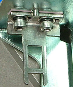
- Use a hex key to remove the two screws securing the interlock operation
key.
- Add the required number of spacers (part number 252-10209A) to the
interlock operation key assembly:
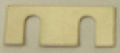
- Reinstall the interlock operation key, by using the marked outline
as a guide.
- Place two strips of masking tape over each end of the interlock’s
entry point:
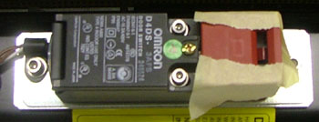
- Close the top rear cover just enough for the interlock operation key
to punch holes in the masking tape.
- Manually open the top rear cover:
- If no punched holes appear on the masking tape, then the interlock
operation key is correctly positioned.
- If punched holes appear on the masking tape, then reposition the
interlock operation key and repeat steps 6-8.
|