Home | Contact Us | Submit Troubleshooting Info | Search | Help


    Output | Software Solutions | Proofing | Color, Screening and Calibration | Scanning | Digital Photography | Consumables | POS


Replacing the CPU Board for ThermoFlex Mid II/Narrow Hybrid with Windows XP


Product

 
  • Kodak® ThermoFlex® Mid II Hybrid
  • ThermoFlex Narrow Hybrid

Operating system


Microsoft® Windows® XP


Background


This procedure describes how to replace the CPU (SBC) board.


Requirements


SBC kit (609-00397) SBC 256K


Procedure


Preparatory steps:

  1. Back up the registry and database. (Download the
    Lotem Backup and Restore Utility .exe file.)
    Note: It is recommended to back up the entire disk. (See Backing Up Drive C or Entire Hard Disk Using the Backup and Restore Tool.)
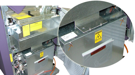
  2. In the ThermoFlex Controller software, open the relevant door to enable you to access the E-box, and then exit the ThermoFlex Controller software.
  3. Turn off the platesetter and disconnect the platesetter from the main power.

Uninstalling the SBC board:

To uninstall the SBC board, you must disconnect any external connections, then open the E-box panel, slide the SBU board out, and disconnect any internal connections, as described following.
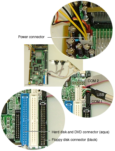
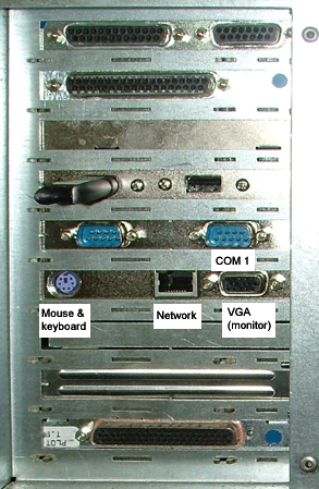
  1. From the E-box, disconnect the following external connections:
    • COM I plug
    • Mouse and keyboard adaptor
    • Network plug
    • VGA plug
  2. Release the locks on the E-box panel and remove the panel.
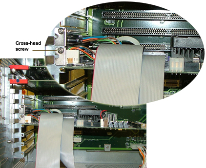
  3. Remove the screw that secures the SBC board in its slot in the E-box and pull the SBC board partially out.
  4. From the SBC board, disconnect the following internal connections:
    • USB ports cable
    • Power cable
    • COM I
    • COM 2
      Note: COM 2 is not connected externally. The internal connection is for future use.
    • Hard drive and DVD
    • Floppy drive
  5. When all connections are disconnected, remove the CPU board from the E-box.

Installing the CPU (SBC) board:

To install the CPU board, you must connect the internal connections to the CPU board, slide the board into its slot in the E-box, close the E-box panel, and then connect the external connections, as described following.
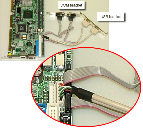
  1. Insert the CPU board partially into its slot in the E-box.
  2. Connect the following internal connections:
    • Hard drive and DVD
    • Floppy drive
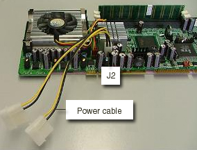
    • Power cable—J2 port

    • USB ports cable—J29 port
    • COM I and COM 2
      Note: Make sure that the flat cable is positioned with the red stripe toward the bracket, as shown.
  1. When all internal connections are connected, push the CPU board all the way into its slot and secure it with the crosshead screw.
  2. Install the E-box panel, using the locks to secure it.
  3. Connect the external connections:
    • COM I plug
    • Mouse and keyboard adaptor
    • Network plug
    • VGA plug
  4. Load BIOS for XP (.exe file), as described in the Creating a BIOS disk and uploading BIOS for Windows XP-compatible CPU procedure.
  5. Connect the main power and turn on the platesetter.

Test


Expose a job and confirm that the platesetter is functioning properly.


Technical contact(s)
 

Content owner: Viki Arviv
See the Escalation page for escalation contacts.

Date submitted
 

26 Nov 2006


    Copyright © 2005 Creo Inc. All rights reserved. Confidential. Back to top.