Cause |
|
The edge detection system repeatedly performs edge detection to locate
the plate edge and returns inconsistent position readings.
The edge detection system performs edge detection several times and finally
locates the plate edge.
The edge detection system performs edge detection and cannot locate the
plate edge.
When the plate unloads from the platesetter and there is no image on
the plate, an error message appears.
Possibilities for the failure include:
- Dirt on the lens, drum, light detector, or edge detection strip
- The plate is not properly attached to the drum
- Faulty focus motor functionality
- Laser power failure
- Power supply failure
- Drum encoder performance failure
- Faulty smart edge detection board
- Faulty LDA head
|
Solution |
|
Note: After each adjustment or part replacement, check whether
the problem is resolved. If not, proceed to the next step.
- Expose a plate and visually verify that the following parameters are
properly adjusted. To adjust one or both of the parameters, see Height/Width Start Image Area Adjustment.
- Wide Start Image Area
- Height Start Image Area
- Run diagnostics to verify that the power supplies have the
correct tolerance and confirm that the tolerance diagnostics tests were
successfully passed.
| Power Supply |
Tolerance |
| VCC 2.5 V |
2.29 V to 2.7 V |
| VDD 2.2 V |
2.24 V to 2.44 V |
| PV 2.2 V |
2.24 V to2.44 V |
If any of the power supplies fail, replace the entire power supply
tray (part number 500-00511A).
- Check the reliabiltiy and accuracy of the Smart Edge Detection test.
- Load a plate to the drum, perform edge detection, and verify that
the edge detection location is consistent.
- If you cannot perform edge detection, clean the following parts:
- Optic lens n the laser diode array (LDA) head
- Drum vacuum holes
Note: Clean the drum vacuum holes while the vacuum is
on.
- Light detector
- Edge detection strip
Note: Clean the edged detection strip with alcohol.
- V
block
- Verify that the plate is attached securely to the drum.
- Verify that the the vacuum pump is turned on.
- If hot spots or bubbles appear on the leading edge of the plate,
perform the steps in the following procedures to resolve these problems:
- In the registry, locate HKEY_LOCAL_MACHINE\SOFTWARE\Kodak\Projects
\Magnus400\EXPOSE and verify the values for the following parameters:
- Focus Relative Move For Edge Detection(micron) is
–100 for 0.15 and 0.2 mm plates.
- Plate Edge Wide Range Detection Enable is 1
- If you have a 42-diode platesetter, check the functionality of beam
0. This beam determines proper edge detection. If required, in the registry,
locate HKEY_LOCAL_MACHINE\SOFTWARE\Kodak\Projects
\Magnus400\IO OBJECTS\LASER GROUP\Laser Group and change the value
of the Plate Edge Detection Laser 0-first,
1-last parameter from 0 (beam 0) to 1 (beam 41).
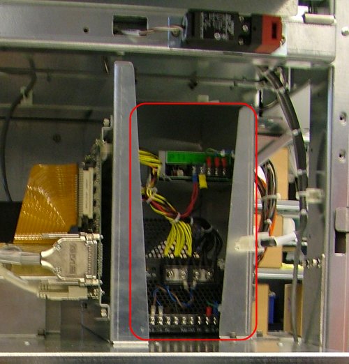
- Verify that the adapter cable (part number 220-01106B) that connects
between the Smart Edge Detection board and the LMCE board is in good
working condition. If the cable is damaged, replace it.
- From the Operations toolbar, select Settings > Media Definitions.
- In the Media Definition dialog box under Media Parameters,
verify that the Thickness value is defined correctly, or change as required.
- If the size of the plate is close to the maximum plate size, in the
registry, locate HKEY_LOCAL_MACHINE\SOFTWARE\Kodak\Projects
\Magnus400\IO OBJECTS\MACHINE and verify that the value of the Height
Start Image Area (mm) parameter is 35. If required, reduce
the value of the Height Start Image Area (mm) parameter by
3 to 5 mm.
- In the registry, locate HKEY_LOCAL_MACHINE\SOFTWARE\Kodak\Projects
\Magnus400\MACHINE and change the default value of the Plate
on Drum Height Axis Absolute Position Error (mm) parameter:
- For ContinuousLoad devices: From 15 (default) to 30
- For MCU devices: From 6 (default) to 30
Note: Changing this parameter will increase stability, but
will decrease throughput.
- Verify that the laser power for edge detection on the platesetter
is correct:
- On Lotem 400 platesetters, go to Utilities > Hardware >
Expose System > Plate Edge Detection System and verify that
the value of the Laser Power(mw) parameter is 30.
- On Magnus 400 platesetters, go to Utilities > Hardware >
Expose System > Plate Edge Detection System and verify that
the value of the Laser Current(ma) parameter is 200.
- Check the focus motor functionality:
- From the Operations toolbar, select Utilities > Hardware
> Expose System > Focus Sytem and double-click Focus
Motor.
- Perform edge detection while monitoring the focus motor movement
in the Focus Motor dialog box.
- Verify that the focus motor position is consistent and that the
optic lens reaches the correct focus level.
- Verify that the focus
values are correct for the 0.15 mm and 0.3 mm plates.
- Verify that the carriage moves smoothly on the V block. There should
be no more than 7 kg of resistance. If necessary, oil
the V block.
- On the platesetter, if diode 0 is spliced, work with the last diode
in the registry.
- Replace the Smart edge detection board.
- Replace the Local3 board.
- Replace the drum encoder.
Collecting Smart Edge Detection Log Files
To send log files to the Response Center (RC) on platesetters with Kodak
Magnus 400 Controller 1.391 software, you must activate the edge detection
log file collector.
- On the destop, select Start > Run.
- In the Run dialog box, type
regedit.
- In the Registry Editor window, locate HKEY_LOCAL_MACHINE\SOFTWARE\Kodak\Projects
\Magnus400\IO OBJECTS\PLATE EDGE DETECTION SYSTEM
\Plate Edge Detection System and change the Detailed Verbosity
Level parameter value from 0 to 1.
- Locate HKEY_LOCAL_MACHINE\SOFTWARE\Kodak\Projects
\Magnus400\IO OBJECTS\PLATE EDGE DETECTION SYSTEM
\Smart Plate Edge Card and change the Detailed Verbosity Level
parameter value from 0 to 1.
A smart edge detection log is created in the Log folder, which you
can then send to the RC.
Note: On platesetters with Magnus 400 Controller 1.392 software,
log files are automatically created.
|