| |
To correct elevation, expose two focus tests on the same plate. The first
focus test uses the first five diodes only, while the second test
uses the last five diodes only. If the elevation angle is correct,
the optimal focus value will be the same for both tests (± 10 microns).
This procedure includes the following sections:
Before you begin
- Find the best intensity for performing the focus tests. See Focus calibration test.
Note: For best results:
- On negative (green) plates, use a lower intensity.
- On positive (blue) platess, use a higher intensity.
Testing elevation
Note: This test is rarely done. Perform this test only to correct
specific instances of banding where the problem was not solved by other
calibrations.
First focus test (first five diodes only)
- In the Magnus 400 Controller software, in the Hardware tree, select
Expose System > Laser System, and right-click Laser Group.
- In the Properties: Laser Group dialog box, locate
the Last Laser Active parameter, write down the current value,
and then change that value to 4.
Attention: Do not change the Last
Laser parameter.
Note: For Lotem 400 FH family platesetters, in the Properties:
Laser Group dialog box, locate the Last_Expose_Laser_Active parameter,
write down the current value, and then change that value to 4.
- Perform the first focus test series at res 100, but do not
unload the plate.
- Return the Last Laser Active parameter to its original value
(that you wrote down in step 2).
Second focus test (last five diodes only)
- In the Properties: Laser Group dialog box, locate the First Laser
Active parameter, and change the parameter value according to the
number of diodes on your platesetter:
On Magnus 400 LDA:
- For a 31-laser diode platesetter, change the value to 27
- For a 41-laser diode platesetter, change the value to 37
On Lotem 400 FH:
- For a 12-laser diode platesetter, change the value to 7
- For a 24-laser diode platesetter, change the value to 19
Attention: Do not change the
First Laser parameter.
Note: For Lotem 400 FH family platesetters, in the Properties:
Laser Group dialog box, locate the First_Expose_Laser_Active
parameter, and change the value according to the number of laser diodes
on your platesetter.
- Offset the image around the drum by 250 mm.
- Using the same range and increments as the first focus series, perform
the second focus test series at res 100.
- Process the plate, and examine the results:
- If the two best focus values are equal or less than 10 microns
apart, the elevation angle is correct.
- If the two best focus values are more than 10 microns apart,
adjust the elevation. See Adjusting elevation.
- Re-enable all laser diodes on the platesetter.
Adjusting elevation
To adjust the elevation so that optimal focus results are returned, first
perform the coarse adjustment, and then if required, perform the fine
adjustment.
Using groups of five diodes, perform the elevation test. See Testing
elevation.
If adjustment is required, using the best focus values
that were returned in the focus test series, calculate the adjustment
(C) according to the following formula: (B–A)/2=C
Use the following example for reference purposes only:

If A is greater than B, lower the back of the telescope tube by (C) microns.
If A is less than B, raise the back of the telescope tube by (C) microns.
Coarse adjustment
- Loosen the three telescope screws (front and rear
screws). Make sure to loosen the rear silver screws, and not
the small black set screws.
 
- If you are using the old elevation jig, perform the following steps:
- On the carriage, remove the focus limit block, and set it aside.

- On the left side of the carriage (from where you just removed
the focus limit block) under the telescope tube, insert the elevation
jig. Make sure the telescope and the surface of the jig are evenly
aligned and fit snugly together.

- Tighten the three telescope screws.
Note: The two screws in the jig limit how far the jig can
go under the telescope.
- Remove the jig, and reinstall the focus limit block.
- Move the focus motor to home position (HP).
- Check the lens and drum clearance, and verify that the clearance
between the drum and the lens protector is 11.5 mm for Lotem 400
FH family platesetters, and 20 mm for Magnus 400 LDA– and Magnus
400 II LDA family platesetters.
Note: See Anti-collision
procedure.
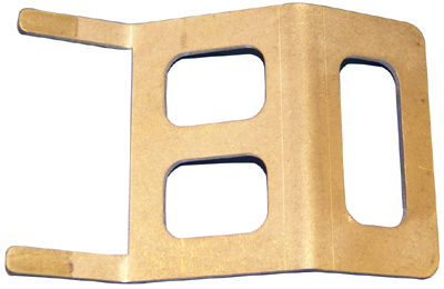
- If you are using the new elevation jig II, perform the following steps:
- Remove the carriage chain bracket.

- Insert the elevation jig II under the telescope tube, and verify
that the elevation is properly adjusted.

- Perform another elevation test series. If you are not satisfied
with the elevation results, perform the fine adjustment procedure.
Fine adjustment
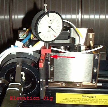
- Install the elevation jig assembly on the back of the telescope tube.

- Set the dial indicator to a known zero position.
Note: Do not loosen the front screw again during the procedure.
Loosening the front screw a second time might cause the front of the
telescope to drop down and upset the adjustment. See step 1
in Coarse adjustment.
- Adjust the telescope tube position according to the adjustment formula
described in Adjusting elevation. After adjusting
the elevation, tighten the two rear screws, and remove the elevation
jig.
- Perform another elevation test series to confirm the result.
- When you are satisfied with the elevation result, re-enable all laser
diodes.
|