Procedure |
|
Safety precautions
- Perform this procedure only if you have completed a thermal head maintenance
course.
- Ensure that you are familiar with laser safety precautions before
performing this procedure. See Magnus 800 platesetter safety guide for service engineers.
- Make sure that none of the thermal 1.7 head’s four red LEDs,
located on the top of the thermal head, is lit during the procedure.
When the write laser is activated, the LEDs are lit.
- Pay special attention to the laser safety labels located near the
platesetter’s bypass switch.
- Wear an antistatic wrist strap throughout this procedure, because
the autofocus laser diode is very sensitive to static electricity.
- The thermal head weighs approximately 23 kg. Observe standard precautions
when lifting heavy objects, and never attempt to lift an object not
within your physical capability.
Backing up files and parameters
In Service Shell, back
up the TH 1.7 NVS parameters.
Removing the existing thermal head
- Shut down the electricity leading to the Magnus 800 platesetter.
- Remove the carriage stopper.
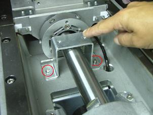
- Remove the protective barrier.
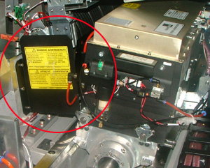
- Manually rotate the carriage until the thermal head base is as close
as possible to the right side door.
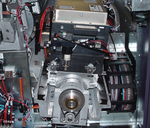
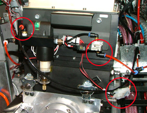
- Disconnect the dehumidifer unit (DHU).
- Disconnect the DHU Molex® connector from the DHU
power connector, located on the thermal head.
- Disconnect the orange air inlet tube from the DHU solenoid.
- Disconnect the black air outlet tube from the DHU unit on the
head.
- Use a 2.5-mm hex key to remove the ground cable from the thermal
head. Replace the screw on the head.
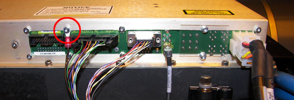
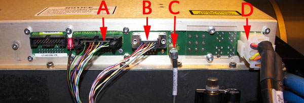
- Disconnect the following cables:
- 20-pin ribbon cable (EH-BP)
- 9-pin EH-BP DB-9 connector (diagnostic)
- Data link cable (EH-BLKHD hotlink)
- 3 x 3 Molex® connector (power cable)
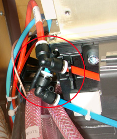
- Disconnect the orange and blue air tubes (originating at the cable
track) from their connectors located on the thermal head.
- Disconnect the two coolant hoses from the thermal head.
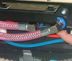
- Use a flathead screwdriver to loosen the screw of the UDRC hose clamp,
and then remove the UDRC hose.
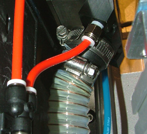
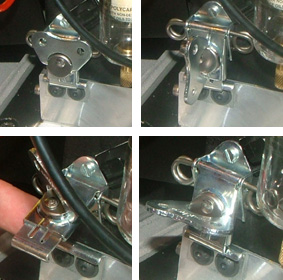
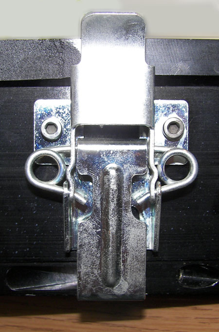
- Release the two butterfly latches located on the home side of the
thermal head and stow them for transport.
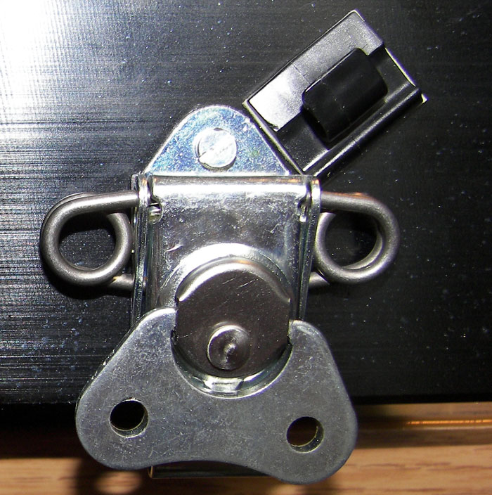
- Unfold the two latch handles.
- To release the latches, rotate the handles counterclockwise.
- Lift the latches away from the latch holders and close the latches
by rotating the handles clockwise.
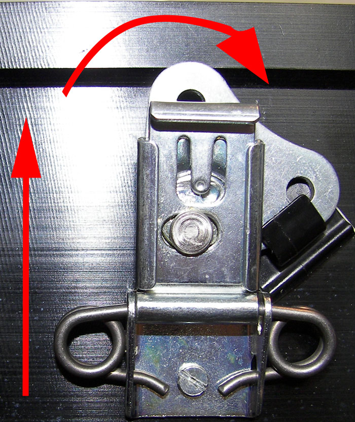
- Fold the latch handles down and flip the latch up. Lock the latch
handle in the clip as shown.
Note:
Stowing the latches prevents them from catching on the latch holders
when the thermal head is removed from the Magnus 800 platesetter.
- Release the single latch on the away side of the thermal head, and
fold the handle up.
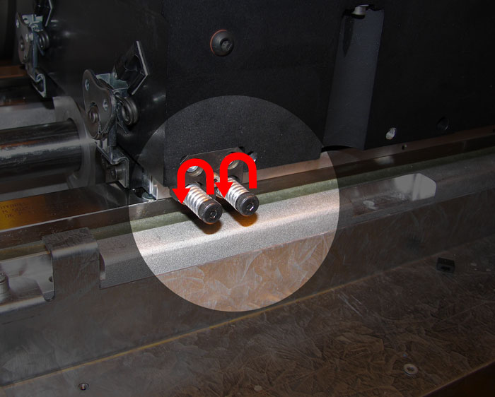
- Unscrew the two spring-loaded screws by rotating them in a counterclockwise
direction.
- Gently remove the thermal head from the Magnus 800 platesetter.
Caution: Be careful not
to bump the lens, shutter, or autofocus actuator
Warning: The TH1.7 head
weighs 23kg. This represents a serious back injury risk.
- Lift the head from a crouched position.
- Keep the weight as close to your body as possible throughout the
lift.
- Place the thermal head on a clean, static-free, work surface.
- Remove the DHU and debris removal nozzle from the head. Save them
for use on the replacement head.
Installing the thermal 1.7 head
- Make sure that the electricity is disconnected from the Magnus 800
platesetter.
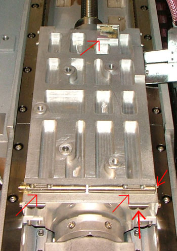
- Apply a small amount of NSK #1 grease (part number 89-0006) to the
five points on the thermal head carriage base:
- Squaring rods
- Tilt screw pad
- Thrust button
- Latch holder on the home side, furthest from the drum
- If this is a replacement head, install the DHU and debris removal
nozzle from the old head.
- Lift the thermal head by its handles and carefully place it onto the
carriage base. Align the V-groove on the underside of the thermal head
with the squaring rods on the carriage base.
Warning: The thermal 1.7
head weighs 23kg. This represents a serious back injury risk.
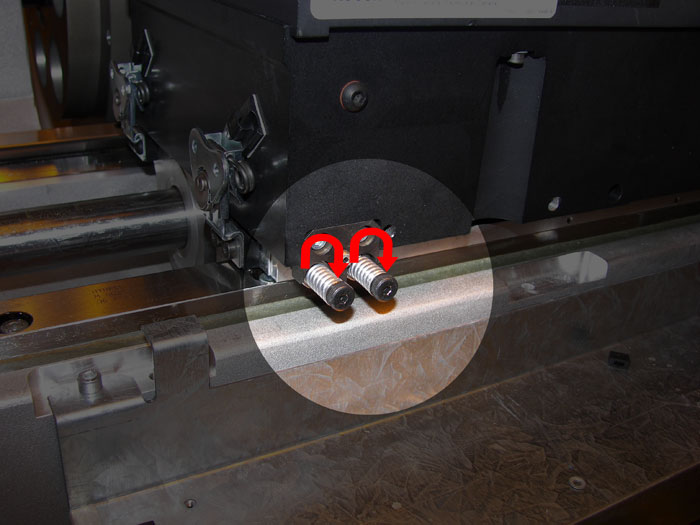
- Screw in the two spring-loaded screws to compress the springs. Do
not tighten them all the way. The springs should not be fully compressed.
- Manually rotate the drum one full turn to ensure that the thermal
head does not collide with the LECs and TECs. If required, move the
head slightly to the rear of the platesetter by adjusting the positioning
set screw (with a 2-mm hex key) in a clockwise direction.
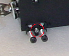
- Lock the latch on the home side, furthest from the drum (latch #1)
onto its holder.
- Route the UDRC hose to the nozzle located on the thermal head. Use
a flathead screwdriver to tighten the clamp’s screw.
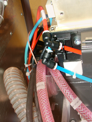
- Connect the air tubes, originating from the cable track, to the connectors
on the thermal head:
- Connect the orange air tube to the orange connector.
- Connect the blue air tube to the blue connector.
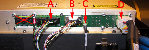
- Connect the following cables to the thermal 1.7 head connector panel:
- 20-pin ribbon cable (EH-BP)
- 9-pin EH-BP DB-9 connector (diagnostic)
- Data link cable (EH-BLKHD hotlink)
- 3 x 3 Molex® connector (power cable)
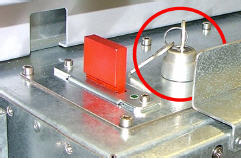
- Remove the screw (depicted below); connect the ground cable witha
replacement screw.
- Connect the DHU unit.
- Connect the DHU Molex connector to the DHU power connector on
the thermal head.
- Connect the orange air inlet tube to the DHU solenoid.
- Connect the black air outlet tube to the DHU unit on the head.
- Connect the two coolant hoses to the thermal head.
- Manually rotate the carriage until there is sufficient room to reinstall
the protective barrier to the optomech assembly. Use a 4-mm hex key
and three screws, coated in Loctite 242 adhesive, to reinstall the protective
barrier.
- Use a 4-mm hex key and two screws to reinstall the carriage stopper
on the optomech.
Zeroing the thermal head
- Insert the red bypass key into the bypass switch.
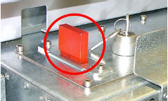
- Make sure that the electricity is connected to the platesetter.
- In Service Shell wait for the following two messages to appear.
Datalink: exposure head coming onlineHead initialized successfully
- Start the Magnus 800 Controller software, and wait until the platesetter
has finished initializing.
- Configure the media-dependent parameters. For the correct media technical
note, see Media
List.
- In Service Shell, type
Magnus>>media N (where N
is the media type being loaded onto the drum).
- In Service Shell, type
Magnus>>set hdm N sr X (where
X is the media type being loaded onto
the drum) to verify whether the surface reflectivity (SR) has been correctly
set.
- In the Magnus 800 Controller software, load a plate onto the drum.
- In Service Shell, type
Magnus>>loaded, and ensure
that the following parameters are correct for the loaded plate:
thicknessmedia typemainscan lengthsubscan length
Zeroing the focus error
Correctly zeroing the head ensures that optimum focus performance will
be achieved over the full range of plate thicknesses.
Latches on the TH1.7 head:
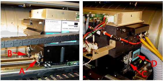
- Latch #1
- Latch #2
- Latch #3
- Latch holder position label
- Insert the focus laser bypass key into the focus laser bypass switch
and rotate the key.
- To zero the focus laser, position the autofocus laser on the plate.
Type the following in Service Shell:
Magnus>>carriage moveto 150Magnus>>drum move 400
Magnus>>head install on
- Verify that the head is correctly positioned on
the carriage. Confirm that none of the latches are trapped between the
head and the carriage.
- While monitoring the
head install on
readout, adjust the positioning set screw to maximize the sum signal
while minimizing the error. Adjust the positioning set screw until the
error is as close as possible to zero.
Warning: When zeroing
the focus error, make sure your eyes are directed either at the same
height as the laser protective barrier or to the left of the barrier.
Warning: Never try to
turn the head positioning set screw when latches #2 or #3 are locked—it
will damage the ultra-fine thread of the set screw. When adjusting the
head position, only latch #1 should be locked.
Typical values are:
- sum (
s): Ideally 1000, if media N sr
is correct.
- difference (
d): Not important for this procedure.
- error (
e): as close to zero as possible; 0 +/–25.
Example:
Magnus>> head install on

          s=1063 d=79 e=-2

          s=1065 d=79 e=-5

          s=1064 d=77 e=4
- Lock latch #2 and note the error value. See the
diagram of latches.
Note: The error value
will change to approximately –50. This is normal.
- Unlock latch #2 and adjust the set screw to adjust
the error to compensate for the change. For example, if the error value
went from 0 to –50 after locking latch #2, move the head to +50.
- Lock latch #2. Ensure that the error value is
between -25 and +25. If the value is out of this range, perform step
5.
- Lock latch #3. Ensure that the error value is
still between -25 and +25. If the value is out of this range, unlock
latch #3 and perform step 5.
- Turn off the data streaming by typing:
>>head install off
- Set the
sr value. Type
>>focus cal reflect

          >>set hdm N sr X
N = the media number
X = the sr value
Completing the thermal 1.7 head installation
- Remove the red bypass key and the focus laser bypass key.
- Reinstall all panels and close any opened doors.
- Make sure the platesetter is in Ready mode.
- Perform drum initialization.
- Load a new plate onto the drum.
- In Service Shell, check the edge detection by typing
Magnus>>edge
          test
.
Checking and adjusting image quality
- Check the processor and media settings.
- Check the processing
line settings.
- Ensure that all media settings are correct.
- Ensure that the thermal head is correctly tuned for the media and
screen set by performing all the procedures described in the media
technical note.
Note:
It is not usually necessary to adjust the bmslope,
bmcurve, and foffset parameters from their
default values (determined during integration). Small changes in wpower
may be required due to slight differences in the processing line.
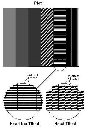
- To ensure that there are no debris artifacts,
image a plot 1 and examine the plate for signs of tick or whisker marks.
See Air Jet Plate Installation Procedure.
- Check that the tilt is set correctly. Inspect
the three pixel horizontal line section of plot 1, using a loupe or
the lenticular tool. The horizontal bars should line up at the swath
boundaries. See Adjusting Tilt on a Thermal Head.
- Check the geometric correction.
Note: This step is applicable
only when a replacement head has been installed.
- Perform rotational
geometric corrections.
- Calculate
and adjust the Mshift and Sshift parameters.
Backing up parameters
In Service Shell, back
up the TH 1.7 NVS parameters.
|

