| |
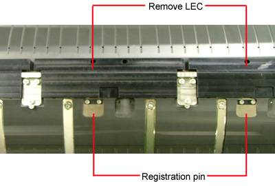
- Remove the leading edge clamps (LECs)
concealing the registration pins.
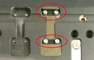
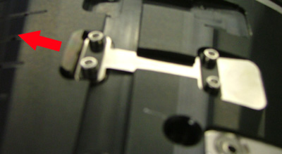
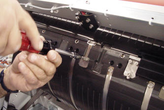
- Remove the four screws securing each registration pin to the drum.
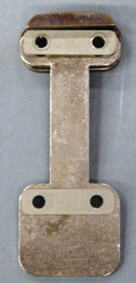
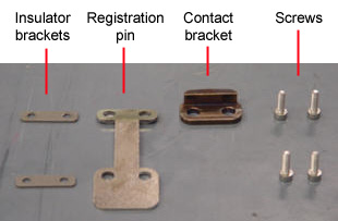
- Remove the registration pin, contact bracket, and the two insulator
brackets.
- Use alcohol to clean the two registration pin pockets that will be
used to house the new pins.
- Position the registration pins, contact bracket, and two insulator
brackets into their new location.
- Use a torque wrench, set to 1.3 Nm, to reinstall the four screws and
insulator brackets. As you install the screws, press the contact bracket
toward the innermost edge of the registration pin pocket.
- Reinstall the LECs.
- If required, reposition the registration pin detectors, located on
the LEC bar, so that the detectors are centrally aligned with the relocated
registration pins on the drum.
- Use the diagram below to reposition the corresponding
registration pin, located on the punch bar, until it is centrally aligned
with the relocated registration pin on the drum.
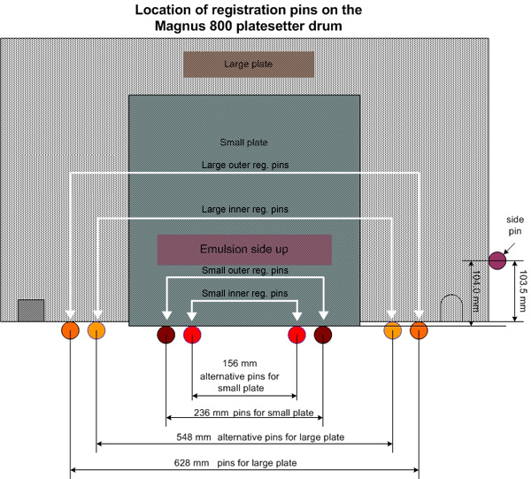
Important: It is essential
that the edges of the plate overlap the registration pins by at least
5 mm.
Use the following table to determine the location of the registration
pins for each plate size.
- If you relocate the large registration pin to the small registration
pin slot, amend the Mshift parameter by -0.5 mm, and amend the machine
Mshift by -500 microns.
- If you relocate the small registration pin to the large registration
pin slot, amend the Sshift parameter by 0.5 mm, and amend the machine
Sshift by 500 microns.
| Large Plates |
| Plate Dimension |
Registration Pin Location |
| 660 mm and larger |
Large outer registration pins |
| 580 mm–659 mm |
Large inner registration pins
|
| |
| Small Plates |
| Plate Dimension |
Registration Pin Location |
| 330 mm–579 mm |
Small inner or small outer registration pins.
Note: If the plate
dimensions are 520–579 mm, ensure the large registration pin
is located on the large outer registration pin slot. |
- The default maximum plate size value for the small registration pins
is set to 620 mm, meaning the small registration pins are expected to
detect any plate with dimensions upto 620 mm.
- Therefore, if you relocate the registration pin from the large
outer registration pin location to the large inner registration
pin location, you must decrease the value of the Magnus800\Software
systems\Loading system\Parameters\Drum - Max Plate Size
For Small Drum Reg Pin to 540 mm.
- If you relocate the registration pins from the large inner registration
pin location to the large outer registration pin location, you must
therefore maintain the default value (620 mm) for the Max
Plate Size For Small Drum Reg Pin parameter.
- Make sure the following registry parameters are set to the values
described below:
Reg pin at default locations (internal):
- OTMCE> set gc PINLoc (1) = 312 mm
- OTMCE> set gc PINLoc (2) = 508 mm
- OTMCE> set gc PINLoc (3) = 744 mm
- OTMCE> set gc PINLoc (4) = 940 mm
Reg pin at alternative locations (external):
- OTMCE> set gc PINLoc (1) = 352 mm
- OTMCE> set gc PINLoc (2) = 548 mm
- OTMCE> set gc PINLoc (3) = 704 mm
- OTMCE> set gc PINLoc (4) = 900 mm
|

