

Home | Contact Us | Submit Troubleshooting Info | Search | Help
Output | Software Solutions | Proofing | Color, Screening and Calibration | Scanning | Digital Photography | Consumables | POS
Home | Contact Us | Submit Troubleshooting Info | Search | Help
Output | Software Solutions | Proofing | Color, Screening and Calibration | Scanning | Digital Photography | Consumables | POS
Configuration Tables | Drawings | Electrical | Registration Pins | Matching Registration / Punch Table Setup | Parts | Service Notes | White Paper
Electronic registration allows the device firmware to detect the correct registration of the metal printing plate to the registration pins on the imaging drum. An electrical circuit is completed by the metal printing plate touching two registration pins at the same time.
The operator of a Semi-Automatic device, or the load mechanism of an automatic device, slides the printing plate into the open leading
edge clamp during the load sequence. If the plate size and location are correct, the plate will contact one driving pin and the correct
sensing pin. The firmware will detect the correctly positioned plate, and go to the next step in the load process.
For details on the registration types, see the Operator Guide for that device in the Media Orientation and Dimesions section.
707-00180A DWG (4 sheets)
| Item | Stored Service Parts | Reference | Notes/photos |
|---|---|---|---|
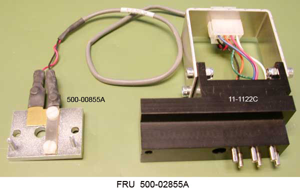
| Registration Probe Assembly
Registration probe Registration continuity switch |
500-02855A
11-1122C 500-00855A |
BOM (FRU) | DWG
BOM | DWG BOM (FRU) | DWG |
Installed on the LEC backbone. See also the Registration page.
 |
| Individual probes | 194-00013 |
There are two standard registration pin layouts: 4-pin and 6-pin.
The different drum diameters do not affect the registration pin layout, just the maximum plate cutoff length allowable. The minimum plate cutoff lengths available also vary:
The pins are slightly staggered to ensure that the plates only contact two pins at a time. This causes a slight plate rotation on the drum which is corrected by the device when the plate is imaged.
There are two rows of edge detect strips (grooves), one near the leading edge clamps and the other about halfway around the drum. These allow the imaging head to accurately locate the side of the plate. For landscape mode, only the edge detect strip near the leading edge clamps needs to be covered, while for portrait mode both strips must be covered.
Note: The home edge of the plate must be over one of the grooves for the edge detect to work properly.
6-pin registration kit: 518-00226B BOM
The 6-pin registration system is used for single or dual plate operation in either landscape or portrait mode.
Dual Plate Loading in Portrait ModeDifferent sets of pins are used for each range of plate sizes, ensuring that both edge detect strips are covered for all plate widths. See design drawing 707-00180 DWG to set up the plate punch to register as closely as possible to the same points used by the Creo device. Note that the side registration pin on the punch will be on the opposite side from landscape mode.
When imaging positive plates in portrait mode, the plate clamping system overlaps the plate by several millimeters. The plate cannot be imaged in these areas, which will be on the sides of the plate when it is on press and will unfortunately pick up ink. This is not a problem when imaging in landscape mode as the plate edges clamped are the same ones that are clamped on the press.
Dual Plate Loading in Landscape ModeThere are three options: large, medium and small. The plate is not centered on the pins for the offset large option. This may affect the accuracy of the punching, depending on how the punch is set up. See design drawing 707-00180 DWG.
Single Plate Landscape ModeOnly pins 3 and 4 are used in this mode. The plates should be centered on the pins. See design drawing 707-00180 DWG.
Three of the six registration pins are drive pins (pins 1, 2, and 4), and the other three are sensor pins (3, 5, and 6). Only one drive pin is active at a time. Any one of the sensor pins can be triggered if contact is made through the printing plate to the active drive pin. Only an active drive pin can provide a current path for a sensor pin.
Diagnostic LEDs are provided for 24V DC, 12V DC, the three drive pins, and the three sensor pins.
4-pin Plate Registration SystemThe 4-pin registration system is used for single plate operation in either landscape or portrait mode.
Single Plate Loading in Portrait ModeDifferent sets of pins are used for each range of plate sizes, ensuring that both edge detect strips are covered for all plate widths. See design drawing 707-00180 DWG to set up the plate punch to register as closely as possible to the same points used by the Creo device. Note that the side registration pin on the punch will be on the opposite side from landscape mode.
When imaging positive plates in portrait mode, the plate clamping system overlaps the plate by several millimeters. The plate cannot be imaged in these areas, which will be on the sides of the plate when it is on press and will unfortunately pick up ink. This is not a problem when imaging in landscape mode as the plate edges clamped are the same ones that are clamped on the press.
Single Plate Loading in Landscape ModeOnly pins 3 and 4 are used in this mode. The plates should be centered on the pins. See design drawing 707-00180 DWG.
The four pins used in 4-pin registration have the same connections as pins 1, 2, 5, and 6 of the 6-pin configuration. This connection scheme allows the electronics and cabling to work for both 4-pin and 6-pin registration without alteration.
Spring probes (pogo pins)The electrical connection between the drum and backbone is made with pogo-pin spring probes mounted on the backbone, which contact the contact block mounted on the home end of the drum. There are six spring probes, one for each registration pin.
The probe assembly is the mounting block that holds the six spring probes, their wiring, and a connector on the backbone.
The punch table setups used for the Trendsetter VLF (280, 504 and 697 mm) can, in most cases, be used for Magnus VLF plates.
| Pin Spacing | Used for Trendsetter VLF Plates | Can Be Used for Magnus VLF Plates |
|---|---|---|
| 280 mm | 394-726 mm wide | up to 610 mm wide |
| 504 mm | 727-888 mm wide | 611-907 mm wide |
| 697 mm | 889-2032 mm wide | 908-2108 mm wide
May also be used for single plates from 889-907 mm wide (but not for dual plates) |
When making modifications to a punch table, refer to the Magnus VLF registration system design drawings (707-00180A).
Special considerations must be made when imaging portrait plates on the Magnus VLF:
When making modifications to a punch table, refer to the Magnus VLF registration system design drawings (707-00180A).
Plate registration on Kodak devices, 719-00328A
Small circuit board to provide isolated 12V DC and to contain the driving and sensing circuitry that interfaces the registration pins to the MCE.
CablesConnect between the MCE and 6-Pin Registration Board, and between the 6-Pin Registration Board and the Probe Assembly.
Power and CurrentThree relay driver outputs on the MCE are used to select which driving pin is active. They are isolated from the registration pins by opto-couplers.
Actuators and Sensors4 pin registration, not dual-plate capable
| Probe No. | 1 | 2 | 3 | 4 | 5 | 6 |
|---|---|---|---|---|---|---|
| Reg. Pin No. | 1 | 2 | NC | NC | 3 | 4 |
| Signal | DRIVE0 | DRIVE1 | SENSOR0 | DRIVE2 | SENSOR1 | SENSOR2 |
| Connector Crimp No | 5 | 1 | 2 | 3 | 4 | 8 |
| Plate Size | Probe Pair | Pin Pair | Drive
probe/pin/signal |
Sensor
probe/pin/signal |
|---|---|---|---|---|
| Small | (2,5) | (2,3) | 2/2/DRIVE1 | 5/3/SENSOR1 |
| Intermediate | (1,5) | (1,3) | 1/1/DRIVE0 | 5/3/SENSOR1 |
| Large | (1,6) | (1,4) | 1/1/DRIVE0 | 6/4/SENSOR2 |
Connector crimp- The crimp terminal in the connector that joins the backbone cable to the spring probe assembly.
Probes - The spring probes or "pogo pins" that make the connection between the backbone and the drum.
Registration pins - The registration blocks on the drum. Pin 1 is closest to the "home" end of the drum.
Signal - The name of the electrical signal used to check for registration.
6 pin registration, dual-plate capable
| Probe No. | 1 | 2 | 3 | 4 | 5 | 6 |
|---|---|---|---|---|---|---|
| Reg. Pin No. | 1 | 2 | 3 | 4 | 5 | 6 |
| Signal | DRIVE0 | DRIVE1 | SENSOR0 | DRIVE2 | SENSOR1 | SENSOR2 |
| Connector Crimp No | 5 | 1 | 2 | 3 | 4 | 8 |
| Plate Size, Two Plates | Probe Pair | Pin Pair | Drive
probe/pin/signal |
Sensor
probe/pin/signal |
|---|---|---|---|---|
| Small (home side) | (2,3) | (2,3) | 2/2/DRIVE1 | 3/3/SENSOR0 |
| Small (away side) | (4,5) | (4,5) | 4/4/DRIVE2 | 5/5/SENSOR1 |
| Intermediate (home side) | (1,3) | (1,3) | 1/1/DRIVE0 | 3/3/SENSOR0 |
| Intermediate (away side) | (4,6) | (4,6) | 4/4/DRIVE2 | 6/6/SENSOR2 |
| Plate Size, One Plate | Probe Pair | Pin Pair | Drive
probe/pin/signal |
Sensor
probe/pin/signal |
|---|---|---|---|---|
| Small | (2,3) | (2,3) | 2/2/DRIVE1 | 3/3/SENSOR0 |
| Intermediate | (1,3) | (1,3) | 1/1/DRIVE0 | 3/3/SENSOR0 |
| Large) | (3,4) | (3,4) | 4/4/DRIVE2 | 3/3/SENSOR0 |