

Home | Contact Us | Submit Troubleshooting Info | Search | Help
Output | Software Solutions | Proofing | Color, Screening and Calibration | Scanning | Digital Photography | Consumables | POS
Home | Contact Us | Submit Troubleshooting Info | Search | Help
Output | Software Solutions | Proofing | Color, Screening and Calibration | Scanning | Digital Photography | Consumables | POS
Control/settings
For the latest conrolled release firmware that supports APL, see the Control/settings page.
Drawings/photos
For APL drawings and photos, see the Drawings/photos page.
FCOs
For APL related FCOs, see the FCOs by Subassembly page.
Installation
For APL installation procedures, see the Installation page.
Maintenance
For APL maintenance procedures, see the Maintenance page.
Specifications
For APL specifications, see the Overview page.
Parts/tools
For information on parts and spares kits, see the APL parts page.
Procedures
For APL adjustment and repair procedures, see the Procedures page.
Reference
For APL related Technical Bulletins, customer Visual Reference Guides, and White Papers, see the Reference page.
Troubleshooting
For APL troubleshooting procedures, see the Troubleshooting page.
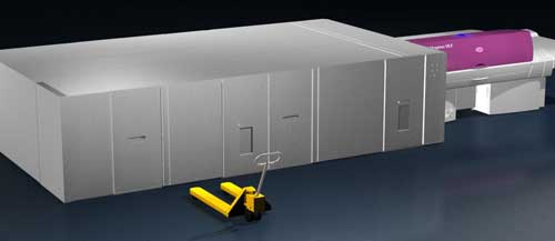
The Automatic Pallet Loader (APL) option for the Magnus VLF replaces the MCU and provides automatic loading of plates from a plate stack located on a pallet. The APL consists of a one segment, two segment, or three segment option and can be configured to support dual pallets in one bay. The major subsystems are:
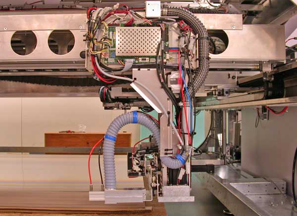
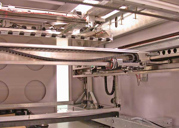
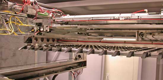
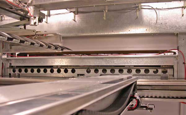

The inductive sensor detects metals using a high frequency electromagnetic field. It is used to detect the height and location of the plate stack.
The load cell sensor is a strain gauge that is used to measure weight. The sensor is factory calibrated and comes with an amplifier as a matched pair. The sensor is used to detect and measure the weight of the plate on the P-cup when the P-cup has the plate corner raised. This measurement is then used to determine if the P-cup has one or more plates. If it only has one plate the device will continue picking, if not the P-cup will lower and attempt the pick again.
The sensor array consists of three reflective sensors positioned in an array such that the device can determine if it is in the correct pick position. The inductive sensors have already determined the approximate pick location. When the picker moves to this position it will pick the plate corner up with the P-cup and the array will be used to ensure the picker is in the correct position based on the sensor readings reflected from the plate corner. If it is not in the correct position, the picker will adjust the X and Y positions accordingly.
The hover cart is an optional device that is used for loading plate pallets into the APL where the space in front of the APL is limited and to reduce operator work load while loading plate pallets. The hover cart rides on a frictionless film of air provided by
air bearings on the underside of the hover cart. The hover cart also uses pneumatic lifters for lifting and lowering plate pallets for transport. For movement parallel to the front of the APL, a rail is fixed to the floor to guide
the hover cart. For maximum effectivity of the hover cart, the floor surface must be flat, smooth, and without cracks or crevices. For details on the floor and air requirements, see the site preparation document for APL: Magnus VLF with APL Site Preparation Guide, English.
The main components of the hover cart are the control handle, the frame, the lifters (in the left and right legs of the frame), and the internal pneumatic control system.
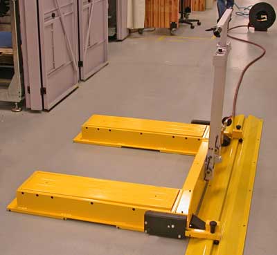
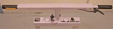
The control handle is used by the operator to adjust the air bearing pressure, turn the lifters on and off, actuate the air bearings, and for directional guidance of the hover cart. The handle can be used in the upright position (straight or rotated) or in a tilted position.
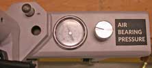
| Air bearing pressure: A control knob on the lower part of the handle is used to adjust the air bearing pressure while moving the hover cart.
Adjust the pressure to 30 psi. If the cart oscillates, then adjust the pressure down until it smoothes out. If the cart is sticking on the floor somewhere, then adjust the pressure slightly higher. |
 |
| Lifters On/Off: A switch on the lower part of the handle used to turn the pneumatic lifters on and off.
After moving the hover cart in under a plate pallet, turn this switch on to lift the pallet off the ground. When the pallet is in position inside the APL, turn this switch off to lower the pallet onto the ground. |
 |
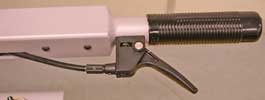
| Handle tilt: A lever on the left side of the handle used to release the handle for tilted operation.
It is often easier to control the movement of the hover cart with the control handle tilted—pull the lever to release the handle. When raising the handle again, it will automatically lock in place in the upright position. |
 |
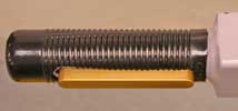
| Air bearing trigger: A trigger on the right side of the handle used to turn the air bearings on and off.
Squeeze the air bearing trigger to move the hover cart with or without a plate pallet. You may need to adjust the pressure while moving the cart (see 'air bearing pressure'). |
 |
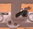
| Handle rotate: A lever on the lower part of the handle used to release the handle for rotated operation.
Use this lever when you wish to rotate the control handle 90 degrees for operation in tight spaces. For example, while moving the cart along the tracks parallel to the APL. |
 |
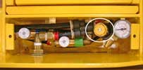
The pneumatic components are housed inside the hover cart frame. Amongst these components are four adjustable air flow control valves (one for each air bearing), and one adjustable control valve for the air lifters.
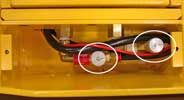
| Air flow control valves: Four adjustable control valves for the four air bearings. These valves adjust the height of the hover cart above the ground.
Although these valves are adjusted at the factory, they may need to be adjusted if hover cart is not equally level with the floor during operation. For example, one corner may constantly be getting stuck. The valves are located below two small panels on the hover cart frame—each panel contains two valves for that side of the hover cart. |
 |
| Lifter control valve: The pressure in the four air lifting bladders is controlled by one adjustable control valve. The higher the pressure, the higher the lifting capacity of the hover cart.
To maximize the life of the air bladders, the pressure must only be high enough to lift the customer's largest (heaviest) plate pallet. Using the largest plate pallet, adjust the control valve until the hover cart lifters raise the pallet off the ground plus another half turn. The lifter control valve is located below one of the small panels that house the air flow control valves. |
 |
See the Control/settings page for the latest conrolled release firmware.
This is a high level overview only. The operator has loaded the pallet(s) of plates into the APL—justified to one side of a segment. They have locked the panels and updated Print Console with the configuration of the loaded pallet(s). The X, Y, and Z directions are along the drum, perpendicular to the drum, and vertical respectively.