Home | Contact Us | Submit Troubleshooting Info | Search | Help
Output | Software Solutions | Proofing | Color, Screening and Calibration | Scanning | Digital Photography | Consumables | POS
Home | Contact Us | Submit Troubleshooting Info | Search | Help
Output | Software Solutions | Proofing | Color, Screening and Calibration | Scanning | Digital Photography | Consumables | POS
For assembly drawings, see the Parts/tools page.
Front view - panel off
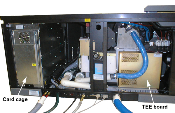
Left side - panel off
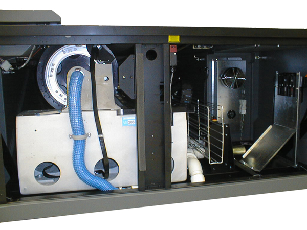
Right side - panel off
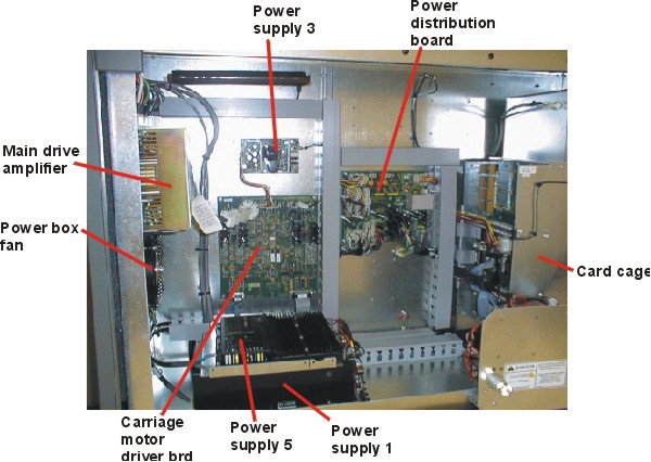
Left rear - Power Box
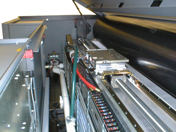
Engine - head removed
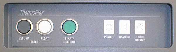
Operator Interface
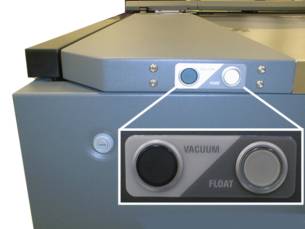
Table Vacuum/Float Buttons
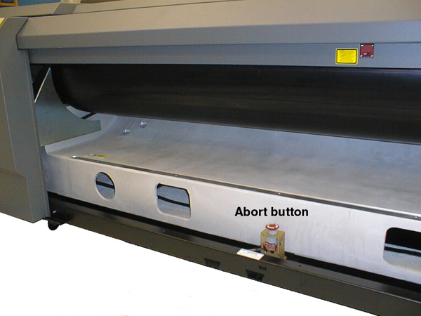
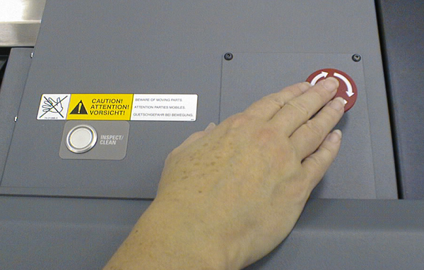
Inspect/Clean and Abort Button
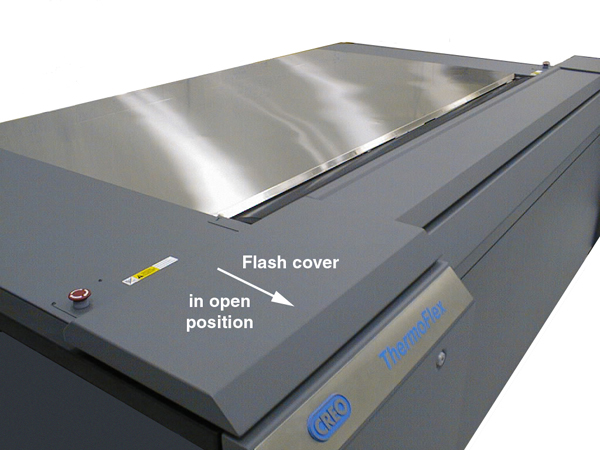
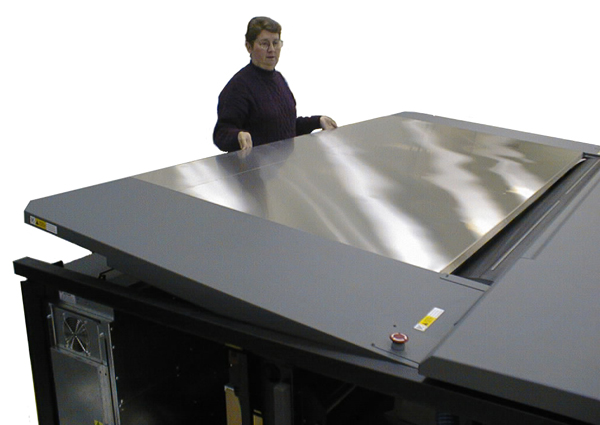
Flash Cover - open position
Table Vacuum/Float Buttons on table
Table Vacuum/Float Buttons on
Operator InterFace
Table Lifting
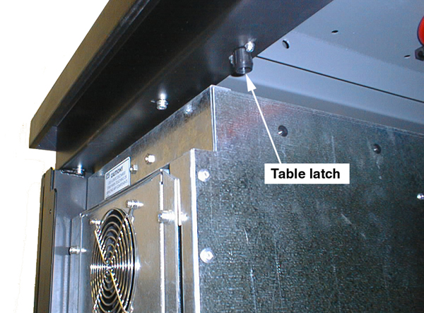
Table Release
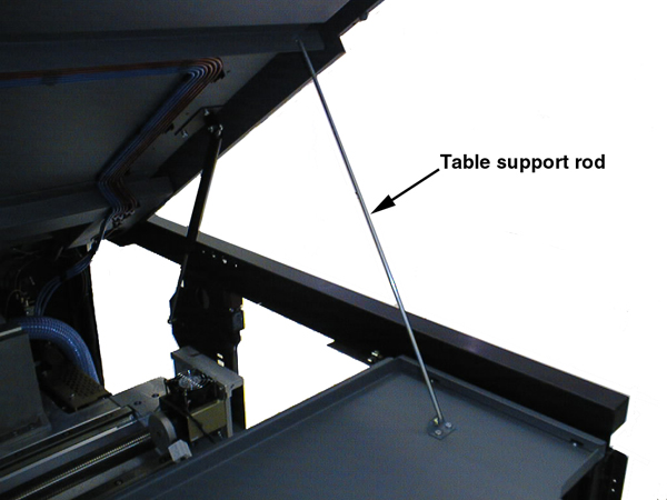
Table Prop Support
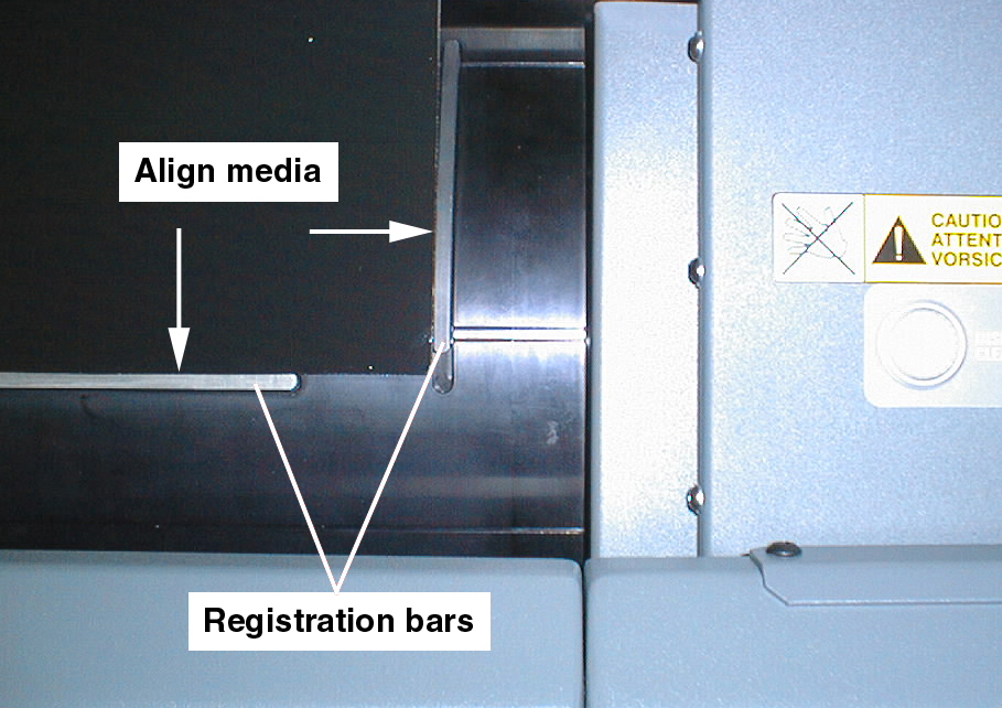
Aligning Media
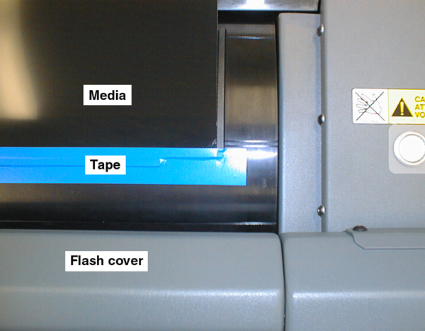
Taped Media
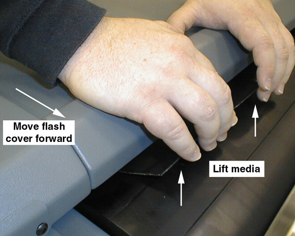
Unloading Media
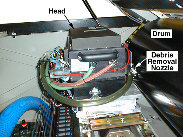
Debris
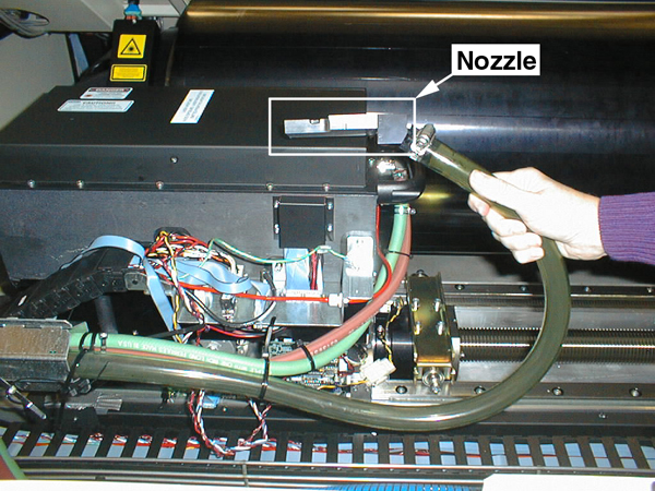
Removal Nozzle Connected (1.7x Head)
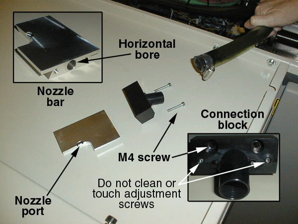
Debris Removal Nozzle
Disconnected (1.7x Head)
Debris Removal Nozzle Assembly
1.7x Head)
Debris Removal Cabinet
 Assembly
drawings are visual representations of bills of materials (BOMs), labeled with
part numbers. They are generally presented with a BOM. That is why, even though
they are drawings, they are located on the Parts/tools
page.