Fan Box (TS8)
Description | Parts | Procedures
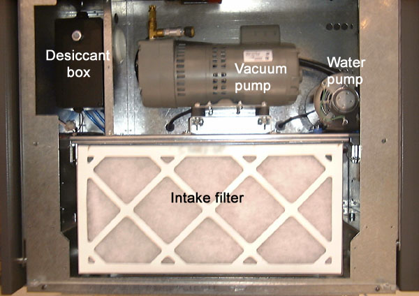
- Located on the right end of the TS8, contains cooling systems, intake
filter and maybe a desiccant box.
- As of FCO E243, there are two versions of the fan box. See write up in FCO
E243 for service implications.
Photos
Prior to FCO E243
As of FCO
E243
For both versions, see Fan box on the TS8
Parts Page.
The main components are:
- cooling fan (15-3486) - one for 1.0, 20W head, two for 1.7, 40W head
- heat exchanger (55-0711)
- thermal blower (15-3155) for 1.0, 20W head
- water pump and motor (50-2071B) for 1.7, 40W head
- intake filter (55-0700)
- water reservoir assembly (50-2173A)
- desiccant box (50-1776A) unless a Dehumidifier Unit is installed on the
head.
- Replace intake filter every month
See Trendsetter 3230/3244 Operator Manual (TS8 version)(03-4213B) for procedure.
- Clean thermal cooling blower inlet screen every site visit - a dirty
screen can reduce cooling for thermal head
- DO NOT REMOVE blower inlet screen
- Check the coolant level in the reservoir, clean the strainer and oil the
pump if necessary. See Cooling system
maintenance.
- Replace desiccant every three months or when indicator turns pink - see
operator manual for procedure