Home | Contact Us | Submit Troubleshooting Info | Search | Help
Output | Software Solutions | Proofing | Color, Screening and Calibration | Scanning | Digital Photography | Consumables | POS
Home | Contact Us | Submit Troubleshooting Info | Search | Help
Output | Software Solutions | Proofing | Color, Screening and Calibration | Scanning | Digital Photography | Consumables | POS
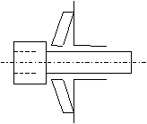 |
Put Belleville washers on screws and bolts as shown in the illustration. |
Before installing the L-conveyor:
The L-conveyor is shipped in three pieces: the frame unit, the table, and the skins.
 Install the frame interface panel.
Use torque wrench wherever possible to achieve proper tightness.
- Place the panel on top of the Trendsetter VLF frame rail.
- Align the panel centerline hole with the system centerline laser.
- Install both sets of fasteners.
- Tighten all fasteners.
- Connect the cable from the inside of the Trendsetter VLF to the interface sensor.
The sensor is on the bottom of the panel, and connects to the two center terminals only (if the switch has four terminals).
Assemble the L-conveyor.
- Assemble the black table shrouds; assemble the long side shrouds first and then the end ones (two helpers are needed). To overcome any alignment problems, partially put all screws in the holes before doing the final tightening. Add the four small corner braces.
- Slide the two guide pins into their spherical bearings on top of the base.
- Put four hard pieces of foam (from crates, appr. 130-150 mm high) at each corner of the shrouded base to keep the table raised for easy access underneath the table.
- Using six or eight (preferred) helpers, orient the table correctly and lift it over the shrouded base and lower it down onto the foam blocks. Center the table horizontally with shroud edges.
- Underneath the table: Attach the guide pins. Attach the table down sensor tabs (4) to the black nut plates of the table height adjustment screws at the bottom of the table. It is correctly orientated when, with the table down, it brings the tab about 10mm in front of the optical sensor (there is only one way to do this).
- Outside the conveyor: Screw in the four black table height adjustment screws (the ones with large sockets) at the cylinders - they might be a little tough to turn because of supporting plastic blocks inside the table. Most of the turning can be done from the top of the table by first removing the plastic plugs and using a heavy flat screwdriver and adjustable wrench as torque arm. Space the screws evenly and leave about a 20mm gap between the nut plate nut and the back of the screw socket.
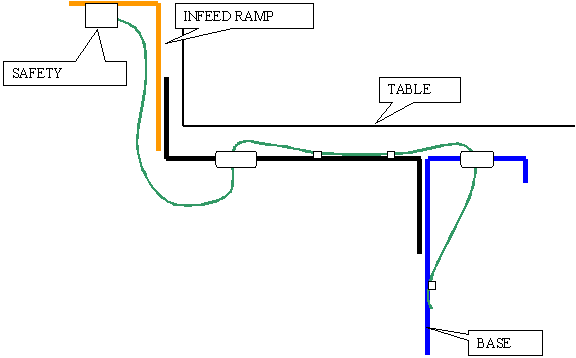
Underneath the table: Slide the Y-axis tubes and cables (in the flex track) through the opening up to the Y-axis channel - have a helper above the table pulling and making sure the cables and tubes do not get scratched. Attach the flex track bracket. Route and attach the X-axis cables (also in the flex track) to the X-axis box terminal; the cable connectors are marked. Route and attach the safety loop cable:
- Underneath the table: Before lowering the table, check that there are no tools or debris left between the shrouds, base, and table. With six to eight helpers, lift the table slightly from the foam blocks (so that guide pins don't come off bearings), and remove the foam blocks (keep your head down in case your helpers lose grip and drop the table). Lower the table slowly onto the four rubber stops, the person underneath must check that the guide pins stay on the bearings.
- Above the table: Connect the Y-axis cables and tubes (all are marked) and put the Y-axis covers on. Fasten the Y-axis push bar to the two tabs (screws into the tabs).
- Outside the conveyor: Attach the X-axis box safety plate with the bent edge inwards.
- Attach the in-feed ramp bracket to the four studs on the side of the shroud at a level so that the bridge plate, which is added later, will be flush with table top.
- Attach the plate exit ramp to match the processor height.
- Attach the side backing panels (plain aluminum) to the table sides. The longest panel has two possible positions (two sets of screw holes). Attach it so that the end is flush with the table end facing the processor. Other end of the panel protrudes by approximately 30mm.
- Attach the decorative panels to the backing panels:
Longest panel to the table side
Combined panel (curved and straight together) to the end opposite the processor
Shortest panel flanks the combined panel
Second shortest panel goes to the side facing the Trendsetter, at the processor end.- Adjusting the assembled conveyor:
Conveyor to TS: First level the conveyor table using the digital level. Adjust the casters (3mm/turn) until the conveyor table height is approximately 5-10mm lower than the TS table height. Adjustment is easier if the conveyer is temporarily raised on blocks to take the weight off of the casters. Use the conveyor lifting lever, #90-1093A, and another wooden safety block to lift the conveyor to insert the temporary blocks.
Conveyor to Processor: This can only be adjusted after the power and air have been turned on and the conveyer is functional. This is done in step 5.
Install the conveyor.
- Roll the conveyor into position beside the Trendsetter VLF. Maintain a 2mm gap between the conveyor flange and the frame panel.
Warning! The sensors on the bottom of the panel will be damaged if the flange and panel overlap.- Align the conveyor centerline to the system centerline laser.
- Align the conveyor flange with the frame interface panel.
Install the conveyor interface plate.
- Place the plate on top of the frame interface panel and the conveyor flange.
- Fit the alignment pins into the holes.
- Press down firmly at both ends to secure the plate.
- Connect the airline to the Trendsetter VLF and the conveyor.
- Make the correct electrical connections for the machine orientation. There are two sets of wires; one for a L-R orientation and one for a R-L orientation.
Align the conveyor to the processor. To adjust the
conveyor/processor height:
Install the outer panels of the conveyor: Curved panels in the front and
back and straight panel on the sides.
Clean the surface of the conveyor.