Home | Contact Us | Submit Troubleshooting Info | Search | Help
Output | Software Solutions | Proofing | Color, Screening and Calibration | Scanning | Digital Photography | Consumables | POS
Home | Contact Us | Submit Troubleshooting Info | Search | Help
Output | Software Solutions | Proofing | Color, Screening and Calibration | Scanning | Digital Photography | Consumables | POS
Objectives:
The conveyor is connected to the machine so that it may be easily moved for service access or for manual operation of the Trendsetter VLF. The interface is a top plate that can be removed without tools.
Before installing the S-conveyor:
 Move the picker to its 'safe' zone near the cassette.
Check that both the Trendsetter VLF main power and the autoloader power
are turned OFF.
Remove both end panels from the conveyor.
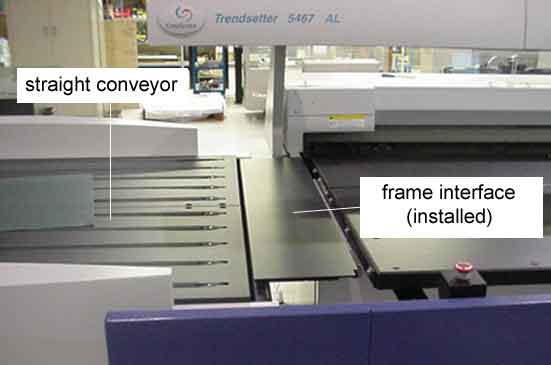
Install the frame interface panel.
- Place the panel on top of the frame rail.
- Align the panel centerline hole with the system centerline laser.
- Install both sets of fasteners.
- Tighten all fasteners.
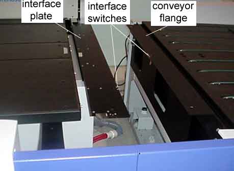
- Connect the cable from inside the Trendsetter VLF to the interface sensor.
The sensor is on the bottom of the interface panel. If the switch has four terminals, it should be connected to the two center terminals only.
Interface sensors Frame interface panel installed
Install the S-conveyor.
- Carefully roll the conveyor to a position 2mm away from the VLF Trendsetter. To protect the frame interface panel, hook hex keys over its edge so that they hang in the gap.
WARNING! Do not overlap the conveyor flange with the frame interface panel. The sensors on the bottom of the panels will be damaged.
- Align the conveyor flange with the frame interface panel. The top surfaces should be flush.
To adjust the conveyor-panel alignment:
- Loosen the large lock nuts on top of the two adjustable conveyor castors closest to the Trendsetter VLF.
- Have a helper take the weight off the castors by using the lever (90-1093A) to lift the conveyor slightly.
- Rotate the adjustable conveyor castors.
- Retighten both large lock nuts.
- Align the conveyor centerline to the system centerline laser.
Install the conveyor interface plate.
- Place the conveyor interface plate on top of the frame interface panel and the conveyor flange.
- Fit the alignment pins into the holes.
- Press down firmly at both ends to secure.
- Adjust the two adjustable conveyor castors furthest from the VLF Trendsetter until the conveyor is level.
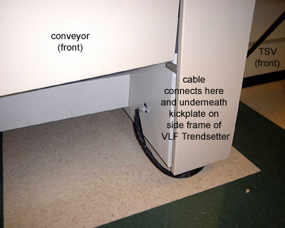
- Connect the cable from the Trendsetter VLF to the S-conveyor.
Cable connected to S-conveyor
Align the S-conveyor to the processor.
To adjust the
conveyor-processor height:
- Rotate both adjustable turnbuckles until the desired alignment is achieved.
Install both end panels on the S-conveyor.
Clean the surface of the S-conveyor.