Home | Contact Us | Submit Troubleshooting Info | Search | Help
Output | Software Solutions | Proofing | Color, Screening and Calibration | Scanning | Digital Photography | Consumables | POS
Home | Contact Us | Submit Troubleshooting Info | Search | Help
Output | Software Solutions | Proofing | Color, Screening and Calibration | Scanning | Digital Photography | Consumables | POS
Calibration | Commands | Description | Diagrams | NVS Parameters | Calibration
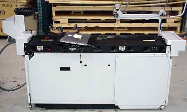
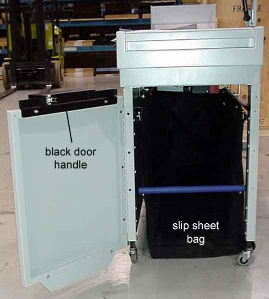
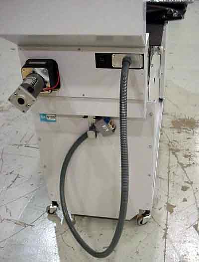
The GT Slip Sheet Removal Unit consists of a compactor, rollers, and a slip sheet bin, and has a black handle on its bin access door (see photo of door handle). Also, the umbilical cable is permanently fixed to the unit (see photo of umbilical cable).
It should not be confused with the earlier SSR version, which has a purple door handle and a removable umbilical cable. This page describes only the GT SSR.
 |
The position of the slipsheet is shown in black. The MCU/SCU is on the left and the device is on the right. |


Displays the status of all compactor-related sensors. Data similar to the following should appear on the console screen:
| Slipsheet Bin status: | |
| SS rlr obstruction sensor | : not blocked |
| Ss Compactor Sensor | : not blocked |
| Ss Compactor Output | : Compact |
| Ss Bag is | : In |
| Slet bin door is | : Closed |
| Slipsheet rollers are | : Open |
| Slipst rollers output | : Open |
| Slipsheet roller motor | : Off |
| Slipsheet roller motor | : not running |
| Slipsheets meters in bin | : 31 |
| Slipsheet unit odometer | : 1088442453 |
For other SSR unit procedures, see the Procedures page.