Home | Contact Us | Submit Troubleshooting Info | Search | Help


    Output | Software Solutions | Proofing | Color, Screening and Calibration | Scanning | Digital Photography | Consumables | POS


Hairlines appear between CT and LW on a RIPed image when CT and LW have the same background color


Product

 
  • Brisque® 4.x
  • Brisque 5.0
  • PS/M 7.x
  • PS/M 8.0

Platform

 
  • All Brisque platforms
  • PS/M: Macintosh®

Operating system

 
  • Brisque: IBM® AIX® 4.2.2, 4.3.1
  • PS/M: Mac OS® 9.x, 10.x

Symptoms


Occasionally, hairlines appear between CT (Continuous Tone) and LW (Linework) on a RIPed image when CT and LW have the same background color.


Cause


One of the following events occurred:

The ratio between the CT and LW res values is not a whole number. For example, LW=100, CT=12, (or if in inches, LW=2540 CT=304.8).
Or,
If the system unit preference is changed from inches to millimeters, the application automatically changes the CT and LW output resolution values in the RIP dialog box. For example, if you defined LW res=2400, and then changed the system unit preference to millimeters, the LW value is automatically changed to 2399.99 in the RIP dialog box.


Solution

Select the following settings:

  1. In Brisque 4.1: in the RIP dialog box, under Output, make sure that the ratio between the LW and the CT values is a whole number. For example, if using inches, LW=2400 and CT=300 (ratio of 1:8).
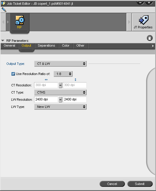
    In Brisque 5.0: in the RIP dialog box, under Output, you can select the Resolution Ratio and enter the LW Resolution. The CT Resolution is then automatically entered, as shown in the dialog box below.


  2. In the RIP dialog box, under Other in Brisque 5.0 or CT Handling in Brisque 4.x, select CT Quality>CT on CT Border>LW Resolution.
  3. In Preferences, it is recommended to change the system unit preference from millimeters to inches.
    Note: When using a Lotem® Quantum platesetter with Brisque, always select inches as the system unit preference.

Note: To use FAF, you should define a template with RIP (with CT quality) followed by FAF. The CT quality process will then run after FAF. This ensures high-quality results that include trap.


See also


Technical contact(s)
 

Viki Bar-on

Submitted by
 

Viki Bar-on

Date submitted
 

26 Dec 2002


    Copyright © 2005 Creo Inc. All rights reserved. Confidential. Back to top.