Home | Contact Us | Submit Troubleshooting Info | Search | Help
Output | Software Solutions | Proofing | Color, Screening and Calibration | Scanning | Digital Photography | Consumables | POS
Home | Contact Us | Submit Troubleshooting Info | Search | Help
Output | Software Solutions | Proofing | Color, Screening and Calibration | Scanning | Digital Photography | Consumables | POS
The Dolev 4press Imagesetter Family is a set of advanced, state-of-the-art imagesetters. The external appearance of the writing engine is radically different to that of its predecessor, the CreoScitex Dolev, but the system contained within its casing is in fact a natural design progression, featuring substantial improvements in all critical performance areas.
Offering highest quality and speed, the formats of the Dolev 4press family are designed to suit the majority of printing presses in use worldwide.
The Imagesetter’s combination of writing engine formats, and the advanced concept and functionality of its digital front end (DFE) raster image processor (RIP) bring pre-press output much closer to press, reducing the need for intermediate manual intervention and increasing process automation.
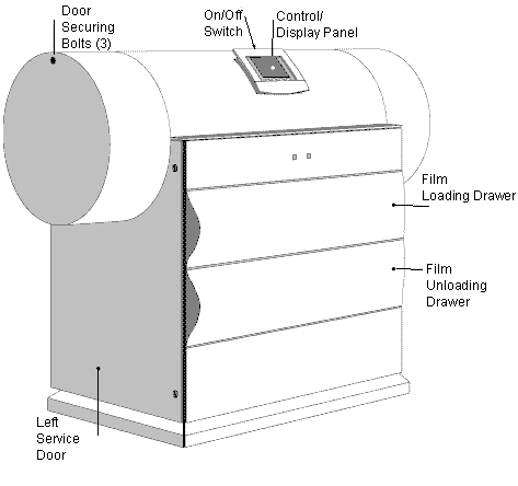
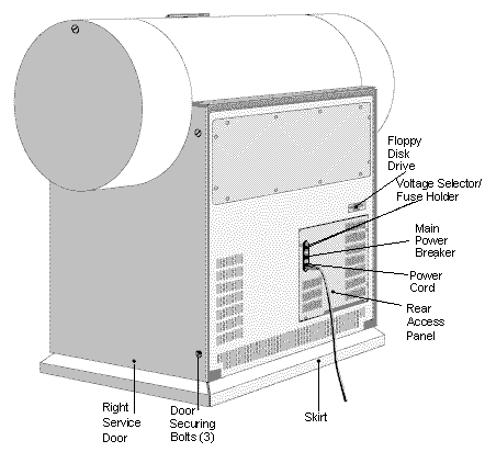
You may open the left/right service doors for the following:
To open the door, proceed as follows:
The procedure for opening the Imagesetter service doors is identical for both left and right doors.
When you are closing the door, secure the three (3) bolts in the following order: bottom, middle, and top.
The Control Panel is located on the upper part of the Imagesetter.
The Control Panel is both an informational tool and an action-oriented user interface.
Control Panel
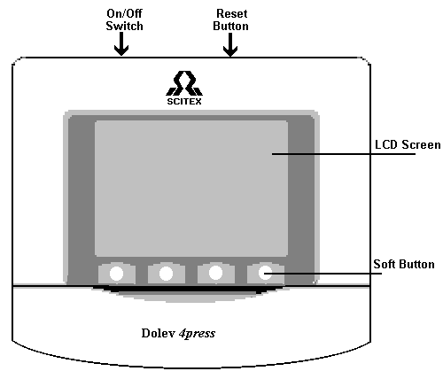 Click to see the full size
The Control Panel consists of the following:
Overview
The LCD screen displays a variety of text (e.g., messages) and graphical representations (e.g., icons, and Imagesetter views) that inform you of the current status of the Imagesetter and of the cassettes.
In addition, it displays menus and windows through which you may perform both basic and advanced operations related to the machine and to the exposure media.
During startup (refer to the Startup section above), the LCD screen is activated.
LCD Screen Following Startup
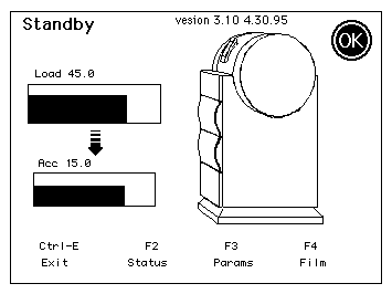
The display on the LCD screen consists of the following areas:
Current Process/Progress Indicator
This area (on the top left part of the screen) displays the name of the process that is currently running, or the current state of the Imagesetter (i.e., Standby or Not Ready).
PROGRESS INDICATOR
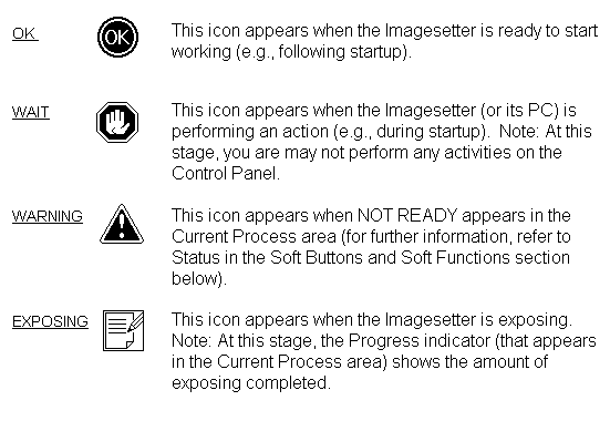
When the Imagesetter is exposing, a Progress indicator is displayed in the Current Process area.
The bar fills from left to right to show the amount of exposing completed.

Imagesetter Micro Version
This area (on the top center part of the screen) displays the number and the date of the Imagesetter Micro software version that is currently installed on the Imagesetter’s PC.
Sample software version number and
data
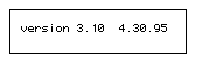
Before starting to work, you need to verify that this software version is compatible with the CreoScitex software version installed on the Host PS/2* (refer to Configuration and Setup, Verifying Software Versions below).
Status Icon
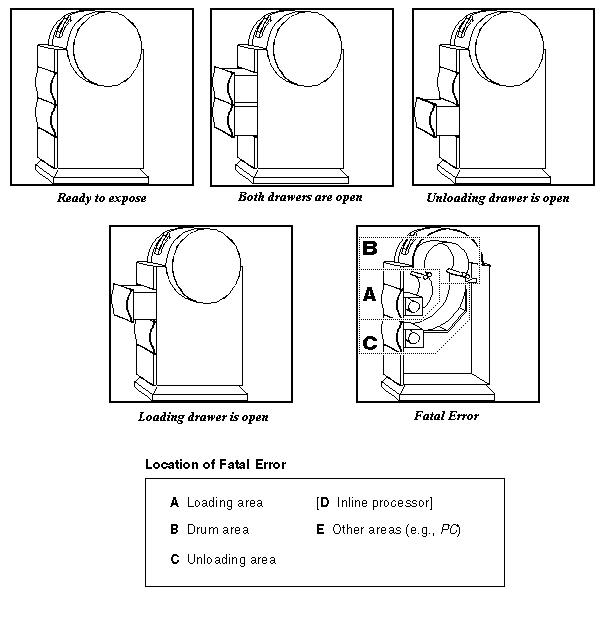
Imagesetter View
Without Inline Processor
This area (on the right part of the screen) displays one of the following representations of the Imagesetter.
With Inline Processor
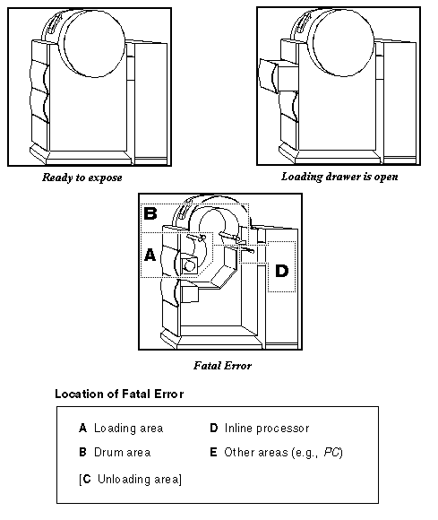
For more information on system error message (that refer to these locations), see Status in the Soft Buttons and Soft Functions section below.
Status of Loading & Unloading Cassette/Inline Processor
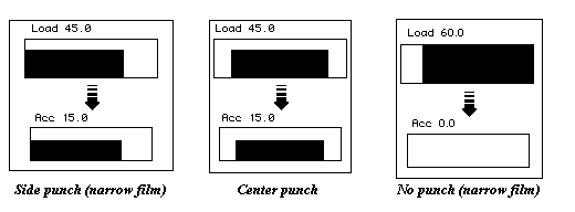
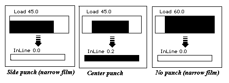
This area (on the left side of the screen) displays one (1) bar that represents the Loading Cassette, and one (1) bar that represents the Unloading Cassette (or Inline Processor, when relevant).
| Length of film | The filled part of the bar represents the length of the film that is currently detected in the cassette/Inline processor (i.e., a completely full bar represents a Loading Cassette with 60m or an Unloading Cassette with 23m). Note: The Inline process bar is either completely full (i.e., when it contains 0.1-0.6 m) or completely empty (i.e., when it contains no film). The actual length of the film (in meters) that resides in the cassette/Inline processor is indicated above the bar (e.g., Load 45.0, Acc 15.0, or InLine 0.2). |
| Punch Option | The width of the filled part within the bar is determined by the currently set punch option (i.e., according to the current location of the left flange of the film spool), and by the width of the currently loaded film (i.e., according to the current location of the right flange of the film spool). |
Center punches are not yet implemented.
STATUS OF LOADING CASSETTE
STATUS OF INLINE PROCESSOR
Soft Buttons and Soft Functions
| SOFT BUTTONS | Four (4) soft buttons are located
below the LCD screen of the Control Panel. Press the desired soft button to activate the function that is indicated on the LCD screen directly above it. |
| SOFT FUNCTIONS | Four (4) soft Functions are
indicated on the bottom part of the LCD screen. Each soft Function indicates the action that is activated when you press the corresponding soft button (i.e., that is directly below it). |
Sample Soft Functions

The functionality related to a specific soft button (e.g., the second on the right) is variable (i.e., depending on the soft function that is currently indicated on the LCD screen).
ACTIVATING THE FUNCTIONALITY
EXITING THE IMAGESETTER SOFTWARE
Press the soft button below Exit to exit the Imagesetter’s software to the DOS prompt (refer also to the Shutdown section above).
PRESS THE SOFT BUTTON BELOW STATUS TO VIEW SYSTEM
MESSAGES.
THE SCREEN REFRESHES TO LIST BASIC MESSAGES.
Basic Messages
Sample basic messages
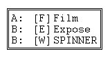
A basic message is composed of the following parts:
Structure of basic message

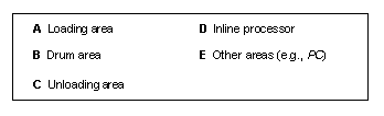
LOCATION A: B: C: D: E:
The letter followed by the colon (:) indicated the location in the Imagesetter that is related to the message
One of the following locations may be indicated:
The letter enclosed by the square brackets indicates the severity of the message.
One of the following severity types may be indicated:
Message Text
The word(s) that follow the [severity] part of the message (e.g., SPINNER) specify the part of the Imagesetter that is related to the message.
Detailed Messages
Below each basic message, a more detailed message appears (in smaller print).
 Several detailed
messages (e.g., [F] Startup failed) appear when you list basic messages (since
they do not have related basic messages).
Sample detailed message
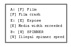
A detailed message is composed of the following parts:
Structure of detailed message
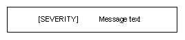
[SEVERITY] [F] [E] [W]
See Severity
Message text
The detailed message tries to explain the nature of the problem that occurred. If this does not suffice refer to the troubleshooting section or to a CreoScitex service engineer.
An exclamation
mark "!" that follows a message (e.g., Open Door !) indicates that
this is an action that you should perform.
In case you need to update the Imagesetter software, insert a 3½" floppy disk into the drive (refer to the Configuration and Setup section further on).
E_BOX to World
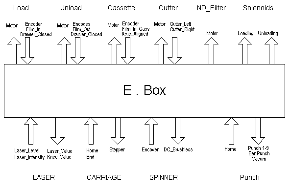 Click to see the full size
E_BOX to D.BOX
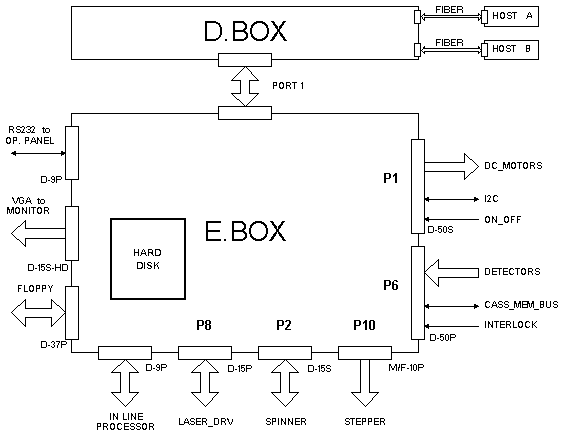 Click to see the full size
E_BOX to
Power Drawer
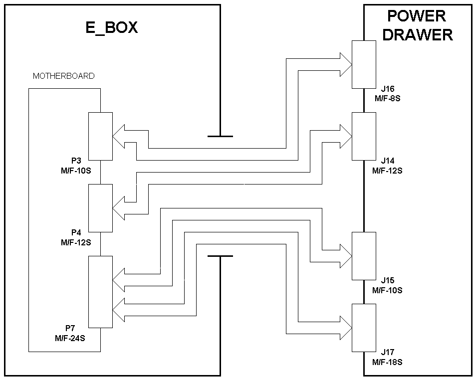 Click to see the full size
GENERAL DESCRIPTION
The Opto Mechanical Control Board controls all the plotter's function excluding the carriage, stepper motor, home position, end position, and strobe corrections.
The board is basedd on a 80196 micro controller.
OMC
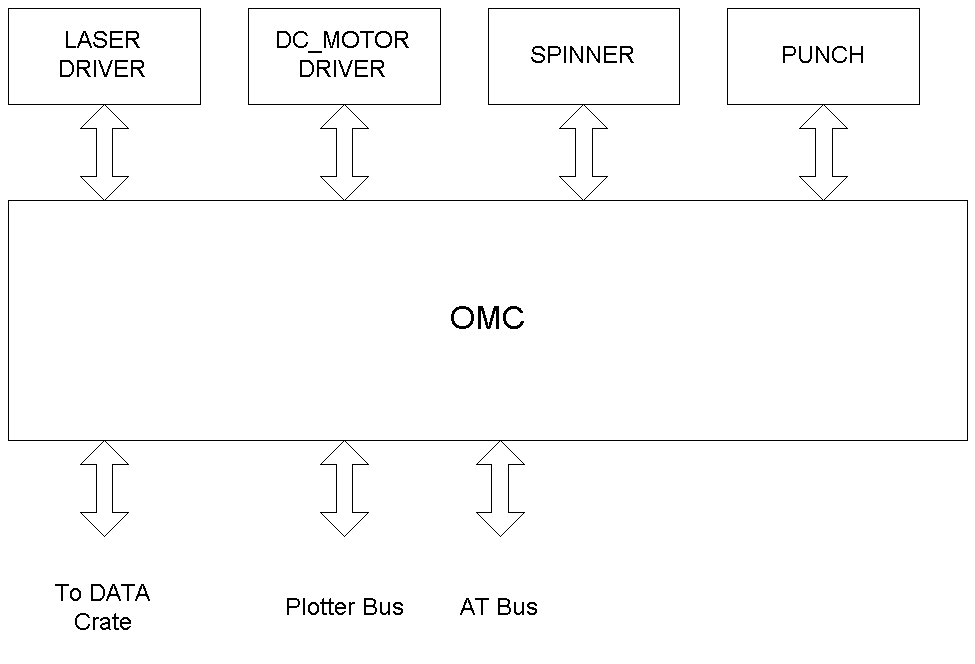 Click to see the full size
CAPABILITIES
GENERAL DESCRIPTION
The Continous Resolution Indexer board controls the carriage's motion via the stepper motor.
CRI
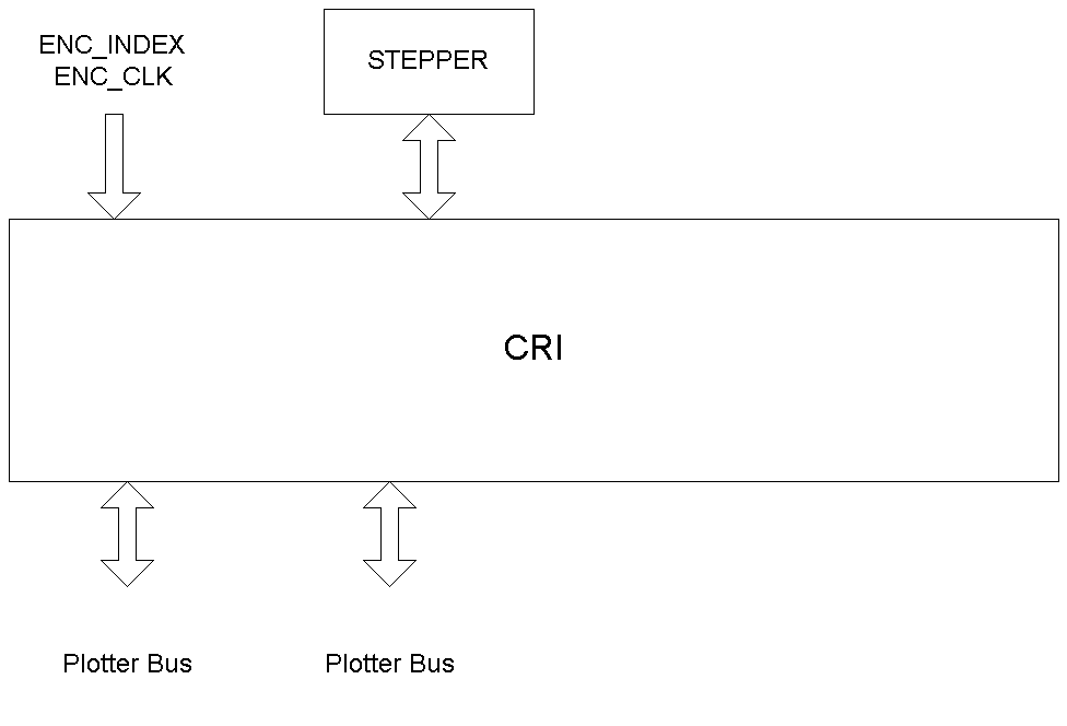 Click to see the full size
CAPABILITIES
FUNCTIONS
E_BOX – DC BRUSHLESS SPINNER DRIVER
DC Brushless Motor - Basics
The construction of DC brushless motors is similar to the AC motor.
Brushless DC motors are different from AC synchronous motors in that
the former incorporate an electrical pulse switching netwoork and spme
means to detect the rotor position.
Board Description
The DC brushless driver is located in the upper right stack of the
E_BOX.
The driver is connected to XXXX on the motherboard. The spinner motor
is responsible for rotating the penta. The DC brushless motor in comparison
to the synchronous spinner has air bearings which enable high spinner speeds
of up to 36000 rpm.
There are two potentiometers on the driver:
T1, T2 don't change
There are eight dip switches on the driver:
DS1 all switches in OFF position.
There are four LEDs on the driver:
| INH LED1 Red |
IC LED2 Red |
COM LED3 Red |
VS LED4 Yellow |
|
| x | Motor working — OK | |||
| x | x | Motor not working — OK | ||
| x | x | Current limit | ||
| x | x | x | No communication signal |
DC Motor Driver
The DC motor driver is located in the upper left stack of the power
driver
boards of the E_BOX.
The board drives the following functions:
| 1. Motors: | Load | Bi_Directional PWM | ||
| Unload | Bi_Directional PWM | |||
| Cassette | Bi_Directional PWM | |||
| Cutter | Bi_Directional On/Off | |||
| ND_Filter | Bi_Directional On/Off | |||
| Spare | Bi_Directional On/Off | |||
| 2. Solenoids: | Loading Drawer | |||
| Unloading Drawer | ||||
| Spare | ||||
| 3. Miscellaneous: | Interlock –
automatic shutdown upon detection. |
|||
| 4. LEDs: | D1 | green | PWR12V | OK |
| D59 | red | high temp | ||
| D4 | red | ND_Filter_Protection | ||
| DD7 | red | spare_motor_protection | (P.S.) | |
| D5 | red | cutter_motor_protection | ||
| D6 | red | cassette_mot_protection | ||
| D7 | red | unload_mot_protection | ||
| D8 | red | load_mot_protection | ||
| DD6 | red | spare_solenoid_protection | (P.S) | |
| D2 | red | unload_solenoid_protection | ||
| D3 | red | load_solenoid_protection | ||
GENERAL DESCRIPTION
The Dolev 4press punch system supports up to nine side punches, one bar punch and one vacuum pump.
The side punches and the bar punch are driven each by a PUNCH_S card.
The vacuum pump is driven by the PUNCH_M card.
PUNCH_M CARD
The PUNCH_M card communicates with the OMC via a 12C bus. The card expands the 12C bus to a parallel PUNCH_BUS. The card drives the vacuum pump.
PUNCH_S Card
The PUNCH_S card drives the side punches and the bar punch. The side punches have addresses between 0 and 11 (dip switch). The bar punch has address 12 (dip switch).
SEQUENCE
After the OMC initiates a punch group sequence, each punch independently completes one punch round (home detector). If a punch is stuck it will generate a current limit which in return will stop the punch.
The Data Unit Handles all data all input to the Dolev 4press and consists of the following board:
Screen Processor LBX + Class Screen
The VLSI Screen Processor is a single board new screen processor developed for a new CreoScitex high-speed applications. It is based on a chip set of three ASICS (defined and designed by CreoScitex) and a very high-speedd local RISC processor.
The VLSI Screen Processor accepts CT and LW pictures in various formats, creates a bitmap image (screen) and sends it to an output device (plotter, proofer, etc.) It can also serve as an interface to a scanner.
Processed image data, CT and LW, is fed to the data system from the Host system by direct memory access. The linework and continous-tone information are merged on-the-fly for the generation of combined linework with screened images.
All commands that establish the specific exposure parameters are sent from the Host computer to the data system. The user selects square, round, elliptical, pincushion or special dot shapes. The system produces the screen angles for cyan, magenta and black separations 30° apart; yellow separation 15° apart, as well as a wide variety of specialized angles.
| SIZE | 30" minimum |
| REPLENISHMENT | Automatic & manual |
| DENSITY | Max. 4.5 |
| VENTILATION | A complete system exists to prevent any evaporation to the imagesetterr area. The ventilation system should work even when the processor is shutdown. |
| FILM TYPE |
|
FILM DIMENSIONS
core: 4 mil & 7 mil
ID: 72mm & 2mm
0=Current in Optocoupler
1=No current in opto coupler
| Feeding Film | Film is advancing at drum exit 0=film motion 1=no film motion |
| Conveyor Ready | No film is present anywhere inside conveyor 0=converyor empty 1=conveyor full |
| Take Film (end of cut) | Take film command from Dolev 4press to
conveyor 0=command is active 1=command not active |
| Processor Ready | The processor is ready to take film 0=processor ready 1=processor busy |
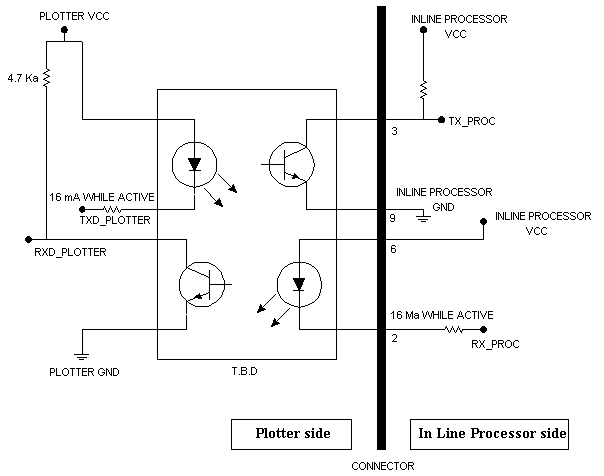
The connector will be through opto couplers. On the plotter side (Dolev 4press) the connector is a 9 pin D-type socket.
| PIN NO. | SIGNAL NAME | SIGNAL DIRECTION | REMARKS |
| 1. | END-OF-CUT | FROM DOLEV 4PRESS | |
| 2. | RX-PROC. | NOT USED | |
| 3. | TX-PROC. | NOT USED | |
| 4. | FEEDING FILM | FROM DOLEV 4PRESS | |
| 5. | GROUND | DOLEV 4PRESS | CHASSIS GND |
| 6. | VCC-PROC | FROM IN L.PROC. | |
| 7. | CONV-READY | FROM IN L.PROC. | |
| 8. | PROC-READY | FROM IN L.PROC. | |
| 9. | GND-PROC | FROM IN L.PROC. |
VCC-PROC, CONVEYOR, and all other PROC signals should refer to the same GND-PROC.
Signals from Dolev 4press to Inline Processor
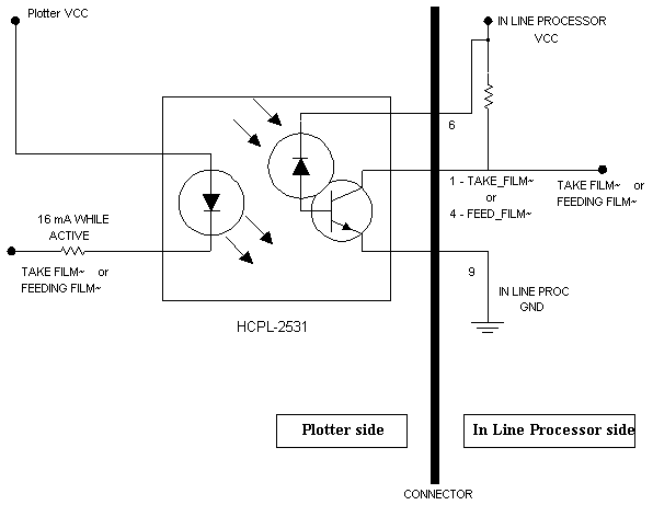 Click
to see the full size
Signals from Inline Processor to
Dolev 4press
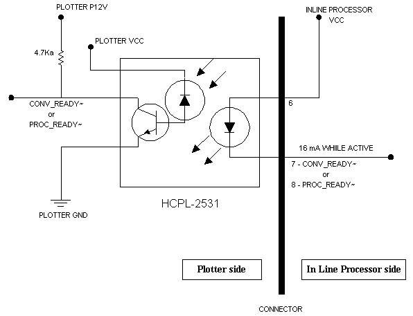 Click
to see the full size
 Click to see the full size
 Click to see the full size