Home | Contact Us | Submit Troubleshooting Info | Search | Help
Output | Software Solutions | Proofing | Color, Screening and Calibration | Scanning | Digital Photography | Consumables | POS
Home | Contact Us | Submit Troubleshooting Info | Search | Help
Output | Software Solutions | Proofing | Color, Screening and Calibration | Scanning | Digital Photography | Consumables | POS
Dolev 800/800V/800V² TIC - Installation
Punch/On-Line Conveyor
Installation
Air Tube, Slug, Wiring and Speed Adjustments
| See FCO17436 | - 05/05/93 | Light Area Harness |
| See FCO 17851 | - 15/06/93 | Manifold installation |
| See FSB 378 | - 19/01/94 | Changes on Punch units |
| See FCO 18908 | - 09/03/94 | Punch Basket Big R |
| See | - 09/12/96 | Dolev 800 Calibration with the Brisque |
| See | - 26/01/97 | Dolev 800 Punch Calibration with the Brisque |
Preliminary
Air Tube Routing
Slug System Routing
Electrical Wiring
Refer to: Waste Slug Tube Routing
- The UNIT IN/OUT tubes are stationary. Route these tubes shortly, without bending and in alignment with their natural curvature.
- The punch rod IN/OUT and slug air tubes move during the punch sequence. Route them together when the punch assemblies are at their OUT position. Carefully check for freedom of movement by moving the punch units manually from their OUT to IN positions and back again. Ensure that these units are not interfering with any of the photo-interrupters.
- Air tubes should be free of stretching.
- Air tubes should not interfere with any moving parts of the Imagesetter.
- Do not tie any air tube. Simply cut them to their final length and poke them into place.
- Air pressure level is 1 atm (14 psi).
- Top cover, rear upper cover and right door are removed.
- All but one punch assembly are electrically disconnected.
- All punch mouths are removed from the punch assemblies.
- All punch assemblies are at their OUT position.
- No film is loaded.
- Optics carriage is at its END position.
- The Imagesetter is completely cleaned of slugs, short black tubes, cable ties, lost fasteners, tools, etc.
- Locate and remove the black tape attached to the internal lower right light cover (under the loading motor on the standard controller side of the Imagesetter). This tape covers a 38 mm hole in the cover, which is used to support the end of the collection tube.
- Install the end cap of the 38 mm black hose into the uncovered hole. Twist the tube 2-3 turns so that it fits inside the cavity next to the standard controller. The open end of the collection tube should be oriented upward, toward the punch assemblies.
Note: On some machines, you will need to attach the special adaptor plate, supplied with the pneumatic system kit, to the internal light cover.
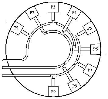
- Arrange the green air tubes so that three (3) tubes will arrive to the single black 38 mm waste slug collection tube.
- Use the natural curvature of the green tubing. Don't attempt to force the tubing against its nature.
- Ensure that the air tubing is fresh, i.e., soft and flexible. Otherwise, an excessive force will be applied to the linear bearing, reducing repeatability and registration quality.
- Ensure likewise that the air tube routing is such that it applies the minimum load on linear bearings.
- Avoid applying excess force on the linear bearing while insert the air tubes.
The air tubing should be inserted a minimum of 20 mm over the black plastic fittings.
- Do not use grease when inserting the fittings into the air tubes.
- The air tubes should not come into contact with any stationary part during UNIT IN/OUT operation.
- Use the absolute minimum of union T- or L-shaped fittings.
Warning: Do not perform a UNIT IN when the optics carriage is at its end position. The punch assemblies can collide with the carriage. Instead, always move the punch units manually.
Waste Slug Tube Routing
Plan ahead before performing air tube routing. It is difficult to disconnect the hoses from the various fittings.
- the PUNCH ROD IN photo sensor connector
- the UNIT IN/OUT photo sensor connectors
Tie together the three moving black air tubes with the moving wires of each punch unit. Do the same to the stationary black air tubes and the stationary branch of wires. Cable ties are supplied with the punch system kit.
- Loosen the securing nut for each valve on the assembly.
- Rotate the air flow adjusting screw for each valve.
Clockwise rotation reduces the air flow.
Counter-clockwise rotation increases the air flow.
- Tighten the securing nut for the adjusted valve.
- All punch UNITS arrive together to their IN/OUT positions within 0.5 seconds.
- All punch RODS arrive together to their IN/OUT positions within 0.3 seconds.
- UNIT IN/OUT stroke is from 0.8 to 1.3 seconds long.
- ROD IN/OUT stroke is from 0.4 to 0.6 seconds long.
It is recommended that you use the Diagnostics module to determine operating cycle times.
Each operation is displayed, including its execution times. An experienced engineer can adjust the system manually in a few moments.
Note that flow controllers control only the air flow exhausted from their cylinder.