Punch Assembly Parts
Punch Hole Linearity Dimensions
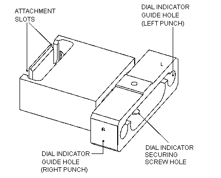
Linearity Indicator Holder
Final Plot Check
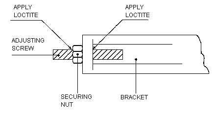
Locking the Assembly Adjusting Screw
This section describes final alignment of punch holes. It
assumes that the punch sequence operates satisfactorily, and that punch hole distances are
correct. You will need to perform several plots during this procedure. Most time will be
spent on peripheral activities such as cover and gauge placement and removal, plotting,
film development, and measurement of result
Punch holes should be co-linear within 0.01 - 0.02 mm. The
best method for testing compliance to this requirement is use of an accurate digital
measuring table. If such a table is available, a plotted and punched film sheet is simply
measured and punch hole locations are subsequently adjusted directly.
Since such measuring tables are generally not available at
the customer site, a second method is used which produces acceptable results. This method
involves plotting of a calibration grid which is used as reference for linearity. This
method ignores image bow, which may be up to 30 microns. When the distances from the punch
holes to the grid lines are measured, it is easy to determine how each punch assembly
adjustment screw should be moved. When adjustments are complete, the final punching line
should be parallel to the image within 0.2 mm. The procedures following describe use of
this method.
An indirect adjustment method entails mounting the punched
film onto the customer's pinbar and observing the mating quality of the pins to the holes.
However, this "eyeball" method lacks accurate feedback for making subsequent
punch assembly adjustments.
Attach the medium and large film rollers to the right flange
of the cassettes.
Attach the medium and large cassettes to the right wall of the
loading/unloading system.
Load large film and measure the width of film which extrudes,
unsupported, from the right drum interior. Take several measurements from different loaded
films for maximum accuracy.
Repeat this procedure for the medium film cassette.
Compare the various measurements. The unsupported film width
for both medium and large films should be from 25 to 28 mm. In case of a larger dimension,
attach the correct film roller to the cassette's left flange. Instruct the customer to
install the film roller in the same way that it is loaded now, including the way the
cassette is loaded into the loading system. Check the results.
Prepare a calibration plot file. Use one of the following
methods:
Create a line of 20 microns in thickness along the film height direction, located in the
vicinity of the punch holes; or
Use the Plot Grid option from the Tools package. Specify a Height Offset value of 754,
with all remaining fields at that default values.
Plot the calibration file, specifying Yes to the Punch option,
with a known offset. Process the plotted film.
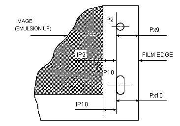
Examine the processed film. Measure the dimensions depicted in
Compare them to the customer's Punched Film Layout Form:
Distance from the film edge to the punch hole center (Px
dimension for every punch hole); and
Plot and measure at two (2) films for highest accuracy.
Refer to the customer-approved punch layout and calculate the
corrections necessary for Px at each punch. Write down these values for reference in later
steps. Be careful not to confuse punch holes.
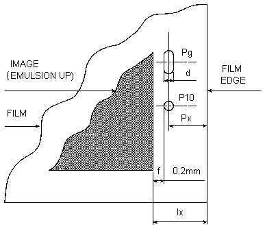
If the f dimension is not between 0.2 and 1 mm, an adjustment
in plot Height Offset will be necessary. If so, calculate the correction necessary in the
plot Height Offset by using the following example:
Given: Ix = 17.9 mm (measured from film edge)
Px =
12 mm (specified in layout)
d =
6.35 mm (punch hole diameter, specified in layout)
f =
0.2 mm (optimal value for manual microscope measurement)
current height offset = 10 mm
Then: new height offset = current height
offset + Ix + Px - d/2 - f
12.525 = 10 + 17.9 - 12 - 6.35/2 - 0.2
If the new height offset calculates to a negative number, change the plotted image file to
compensate, perform a new plot, and measure I again.
Install the linearity indicator holder (Cat. No. 290B36736) on
the first punch assembly.
Remove the punch mouth (Refer to ) from the assembly by loosening its two (2) #6 securing
screws, and replace its with the indicator holder. (The securing holes are slotted to
allow quick removal. There is no need to remove the screws.)
Using the punch utilities on the control panel, perform a UNIT
IN movement.
Install the indicator gauge into its place in the holder.
Refer to The indicator tip should rest on the punch assembly base. Reset the indicator
gauge to zero.
Loosen the punch assembly adjusting screw. (Refer to ) Slowly
rotate the adjusting screw (thereby changing the UNIT IN position) until the indicator
reading is identical to the value calculated in Step 9. Be sure to lock the 1/4- inch
securing nut following the adjustment.
Caution: 1. When adjusting the 1/4-inch securing nut, hold the punch assembly
firmly to minimize loads on the linear bearing. 2. Do not perform a UNIT IN/OUT with the
indicator installed. This may damage the indicator's delicate mechanism.
Remove the indicator and perform UNIT OUT.
Repeat Steps 11-14 for all punch assemblies. When completed,
perform UNIT OUT and return to the Standby prompt in the Imagesetter operating panel.
When positioning of all punch units is completed, lock the
adjusting screw securing nuts of each assembly into place by applying Loctite. The locking
material should be applied in two places along the adjusting screw.
Add all installation paperwork (e.g., Punch Film Layout Forms,
Customer-approved Layout, Order List, etc.) to the on-site Dolev technical folder. Be sure
to include handwritten calculations.
This completes the final adjustment of the punch system. You
should now plot some actual customer files to observe the overall registration quality of
the Imagesetter.