Home | Contact Us | Submit Troubleshooting Info | Search | Help
Output | Software Solutions | Proofing | Color, Screening and Calibration | Scanning | Digital Photography | Consumables | POS
Home | Contact Us | Submit Troubleshooting Info | Search | Help
Output | Software Solutions | Proofing | Color, Screening and Calibration | Scanning | Digital Photography | Consumables | POS
Dolev 800/800V/800V² TIC - Installation
Punch/On-Line Conveyor
Installation
| See FCO17436 | - 05/05/93 | Light Area Harness |
| See FCO 17851 | - 15/06/93 | Manifold installation |
| See FSB 378 | - 19/01/94 | Changes on Punch units |
| See FCO 18908 | - 09/03/94 | Punch Basket Big R |
| See | - 09/12/96 | Dolev 800 Calibration with the Brisque |
| See | - 26/01/97 | Dolev 800 Punch Calibration with the Brisque |
Overview
Punch Assembly
Position Calculation
Punch Assembly Installation
Position Adjustments
Air Hose Installation
Electrical Harness
Installation
Trial Punch Sequence
Trial Inspection
Refer to figures:
Dolev 800 Punch Ruler
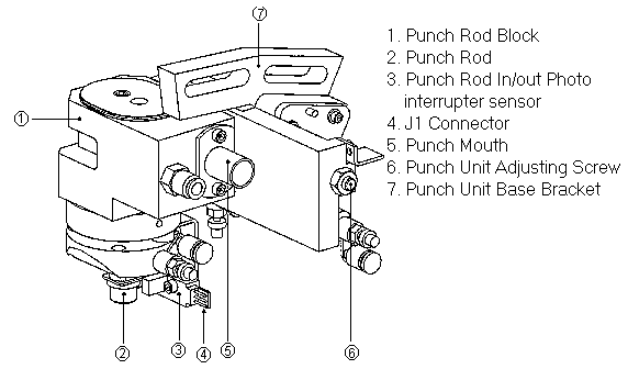
Punch Assembly Parts
Installing the Slide and Ruler Gauges
Punch Adjustment Gauge Position
Punch Adjustment Gauge Detail
Punch-to-Film Radial Distance
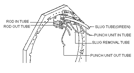
Assembly Air Tube Connections
This is the main part of the punch installation. The complexity and duration of this part depends mostly on the following aspects:
Hint: Preparing materials at the CreoScitex office will save 1 to 2 hours of work in the field. Refer to Section , Off-Site Preparation. Additionally, Punch Unit position calculations (Steps 1 and 2) may also be performed off-site, further reducing time in the field.
- Prepare the ruler by clipping off the punch assembly outlines from either side of the drawing. These outlines are used to simulate placement of the punch assemblies on the flange. Note that these outlines represent either
Right or Big punches. To simulate a Left punch, simply flip the Right outline over and use its backside.
- Referring to the exact specifications in the customer-approved layout, position the appropriate punch sub-type (Right, Left or Big) in its specified location on the ruler.
- The lower endpoint of the Punch Rod Axis indicator line (the end inside the small circle) should be trapped to the center of the cross hair circle inside at the ruler's center.
- The upper endpoint of the Punch Rod Axis indicator line is used to locate the punch at its exact location on the circular millimeters/inch ruler. Note that the ruler's origin falls at the punch minimum line marking, and not at the film edge.
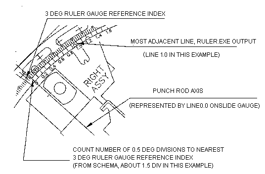
- After positioning the punch assembly on the punch ruler, examine the schema and count the number of 0.5 divisions between the Punch Rod Axis and the nearest 3 index mark. Write this number next at the current punch assembly location on the schema. It will be used during installation.
- At the Enter Distance... prompt, type in the punch hole distance from the film edge, reduced by 55 mm.
- Enter the current punch assembly sub-type at the Right/Left prompt; type R for a Right or Big sub-type, and L for a Left sub-type.
- Write the RULER application output (a number between 0.0 and 1.7 mm) on the schema.
- Repeat the RULER calculation for each of the punch assemblies.
Caution: Do not open by mistake any of the eleven 1/4-inch screws which are used to attach the right flange to the Imagesetter drum (Refer to ) 2929888024002057.
- Referring to the schema you have prepared, identify the two (2) 1/4-inch screw tappings on the right flange of the Imagesetter that will be used to secure each of the punch assemblies. Use the two outermost tappings.
- Install the punch assembly by its base bracket, using two (2) 2-1/4-inch x 1.25-inch screws, with lock washers and washers. Tighten the screws only partially, to allow manual adjustment of the assembly to its final position.
Position the punch assembly exactly as seen on the schema, relative to its two 2-1/4-inch screws. This will make later adjustments easier.
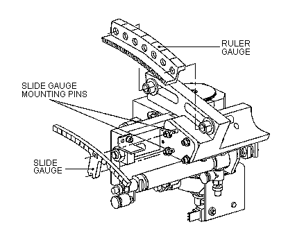
For purposes of rough placement, the arced surfaces of the drum and the punch assembly base should coincide.- Install the two (2) punch assembly adjustment gauges: the slide (Cat. No. 282B36308) and the ruler (Cat. No. 282B36307). Refer to
Installing the Slide and Rule Gauges
Note the position of the semi-circular guide hole on the slide gauge. For Right punch types, the guide hole should be on the right; for Left punch types the guide hole should be on the left.
When placing the ruler gauge on the 2-1/4-inch screw heads, hold it firmly for an accurate reading.
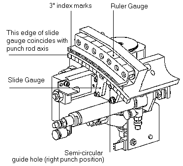
- Ruler and slide gauge positions when making punch adjustments are depicted in Rotate the punch assembly (and with it the slide gauge) away from the 3º ruler gauge reference by the same number of 0.5º index divisions as calculated in the prepared schema (Step 1c). Be sure to refer to the same 3º index mark as shown in the schema.
Punch Adjustment Gauge Position
Punch Adjustment Gauge Detail
- Rotate the punch assembly until the slide gauge line number (the output obtained from the RULER application) coincides with some line on the ruler gauge. If Step d was done correctly, the required rotation will be less than two (2) ruler gauge 0.5º divisions.
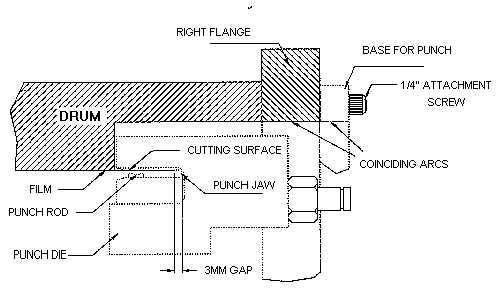
- Set the punch rod to the OUT position. Moving the assembly back and forth manually, adjust the punch radial distance to effect a smooth interface between the punch cutting blade and the film edge. On contact, the cutting surface should "lick" the film, without bending it. Refer to
Punch-to-Film Radial Distance
Hint: Direct a bright light into the drum from the opposite end of the Imagesetter to make inspection of the punch-to-film easier.
It may happen that the punch jaw collides with the film edge at the UNIT IN position. In such a case, change roughly the unit IN position by rotating the adjusting screw clockwise. (Refer to ) Remember to retighten the securing nut after doing so.
- Adjust the punch assembly angular orientation to assure that the punch rod axis is directed towards the drum center. To achieve the best angle, simply verify that there is a uniform gap between arcs of the slide gauge and the ruler gauge.
- Repeat the previous four steps until all the punch assembly positioning requirements are met. Lock down the two (2) 2-1/4-inch screws of the punch assembly. Check punch assembly positioning again after final locking.
Note: Do not hesitate to tighten the two 2-1/4-inch x 1.25-inch screws to the end.
- Repeat Steps d-k for the remaining punch assemblies.
- All units should be at the OUT position.
- All punch rods should be at the OUT position.
- No air leakage not even a small leakage should be occurring.
- No tube or wire should be stressed, stretched or warped.
If air leakage should occur, isolate the source. When tightening air fittings, remember to hold the assembly firmly, to minimize loads on the linear bearing.
| PARAMETER | TABLE OPTION | OLD VALUE | NEW |
| Plotter Type | Factory Tables > Plotter Setting | DOLEV800C | DOLEV800PC |
| Punch Mode | Factory Tables > Plotter Description | 0 | 1 |
| Punch Offset | Factory Tables > Plotter Description | 0 |
- Smooth edge
- No sign of scratches around the holes on either side of the film
- No sign of plucking around the holes
Check for oil marks on the film around the punch holes. If stains appear, clean the punch assembly intensively and check that the air system filter and dryer are connected.
In the event of punch hole placement problems, return to the punch assembly installation procedure and make all necessary corrections. Be sure to readjust affected units for all placement dimensions (radial distance, orientation angle, etc.) If you must move more than one punch assembly, choose carefully the units to reinstall, taking into consideration both ease of access and minimum adjustment.
Note: In the event a substantial difference exists in punch hole distance between the customer's pinbar and the customer-approved punch layout, consult with the CreoScitex specialist.