The Film Feeder Loading Shaft is located on the
optomechanical assembly. The assembly drives the loading wheels (#72). The wheels load the
film onto the drum when operating in a forward direction. The wheels unload the film when
working in reverse direction.
Two engineers are required when removing the Feeder Shaft
assembly. Do not attempt to remove the system from the imagesetter unless at least two
engineers are present.
Prepare a work space upon which you can place the assembly.
At the front of the imagesetter, unfasten the screws
(#169,14,15) securing the metal strip (#83) to the spring plate.
Release the tension on all nine of the film guides
(#58,57,61). Loosen the screws (#85,164) and the spring (#86).
Release the set screw (#161).
Remove the feeder motor from the chassis (#115) without disconnecting the
wires. See Feeder
Motor Replacment.
Rest the motor gently on a support.
Insert the Feeder Loading Shaft Extraction tool (Cat. No.
280A34173) onto the Feeder Shaft. The engineer on the left of the loading shaft holds the
shaft stationary. The second engineer turns the extraction tool knob clockwise until the
bearing on the shaft is released from its housing.
Gently pull the shaft and place the 18 red loading wheels
(#72) and the 34 black loading spacers (#71) on a clean surface. Take care to maintain the
proper order of the wheels.
Pull the shaft completely out of the housing and put it aside.
Unpack the new shaft and check that the two bearings (#70) are
well attached to the shaft. If not, glue them with Loctite. Make sure that the shaft is
clean.
Place the new shaft into the right bearing. Put the spacers
and the loading wheels back in the correct order.
Insert the Feeder Loading Shaft Extraction tool (Cat. No.
280A34173) onto the Feeder Shaft and push the Feeder Shaft into place.
Position the cross adaptor, cleaned and with a thin coating of
new grease, in its place.
Assemble the Feeder Motor in its place and tighten the four
screws.
Fasten the screws (#169,14,15) securing the metal strip (#83)
to the spring plate. check the parallelism of the loading shaft (#34 in load procedure.
Set the tension on all nine of the film guides (#58,57,61).
Tighten the screws (#85,164) and the spring (#86) to achieve the correct tension. For help
setting tension, refer to the next section. Re-install the funnel.
OptoMechanical Assy - Loading Shaft LEFT View (zoom
image)
OptoMechanical Assy - Loading Shaft RIGHT View (zoom image)
Power off the imagesetter using the control panel ON/OFF switch.
Open the left and right service doors.
Remove the light-proof cover from both sides.
Remove out the loading system from the machine.
Remove the two left and two right film guides ( # 57, 58 , 61 ), by loosening
the screws ( # 85 ).
Move the carriage to the centre of the drum using the handle.
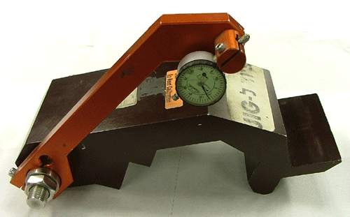
Using the feeder shaft jig check the adjustment of the shaft: (feeder shaft
jig: 280A35802).
The shaft should be parallel within 20 microns on both directions.
Check that the shaft is inside the drum between 200 to 250 microns.
Check that the hight is within limits on both sides - according to the jig.
If adjustment is needed release ( just little ) the two screws on the right
side ( # 114 ) and one screw on the left side ( # 27 ). In order to release
the left screw rotate the spreader wheel to the point that the hole is on
the screw.
Adjust the feeder shaft according to the tolerance.
The film guide tension adjustment sets the tension between
the loading wheels and the loading shaft wheels (film guide wheels). The tension is 200 -
300 g.
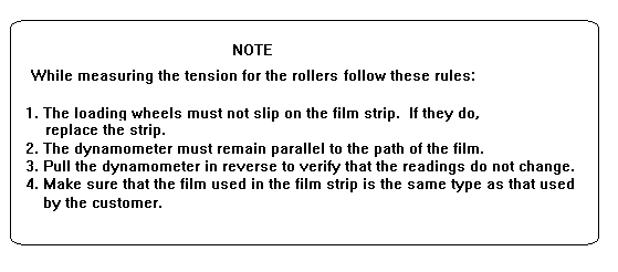
Note: Remember to use the same film type as the
customer uses!
Prepare the film strip and hook apparatus.
Run the Feeder motor forward.
Insert the film apparatus between the Loading shaft wheels and
loading wheels. Hold the apparatus securely to prevent the film from disappearing within
the drum.
Use the dynamometer to measure the tension exerted by the
wheels on the film.
You want to adjust the tension to 300-350 grams. To achieve
this, turn the screw (#85). A turn of the screw tightens or loosens the spring and sets
the tension. Then use the locking screw (#168)
Pull the dynamometer forward and reverse to see that tension
varies and stabilizes.
Tighten the shaft screw (#85) to observe the tension rise.
Lower the tension to 200-300 g. and rotate the feeder motor
forward. Make sure that the tension is the same for all pressure rollers. Check that the
tension is acceptable.