| |
- In Magnus 800 Controller software, raise the Magnus 800 platesetter
cover and hood.
- Remove the platesetter front panel.
- Single-cassette autoloader: remove the cassette tray.
Multi-cassette autoloader: make sure that there are no cassette trays
inside the multi-cassette autoloader.
- Shut down the power supply leading to the platesetter, single-cassette
autoloader, and multi-cassette autoloader.
Platesetter
Alignment system (500-05317A)
- Remove the existing alignment system.
- Install the upgraded alignment system.
The upgraded alignment system (500-05317A) has a longer leadscrew and
larger covers than the existing alignment system.
Note: See Calibrate
the platesetter alignment system for information regarding the alignment
system parameter settings.
Permanent table (500-05316A)
- Remove the existing permanent table.
- Disconnect the air pressure leading to the platesetter.
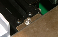
- Remove the two screws (one per each side) securing the permanent
table to the platesetter chassis.
- Disconnect the two hoses connected to the shutter cylinder.
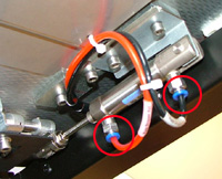
- On the right side of the platesetter, cut the two cable ties.
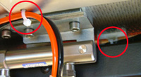
- Remove the screw securing the safety cable to the platesetter
chassis.
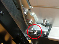
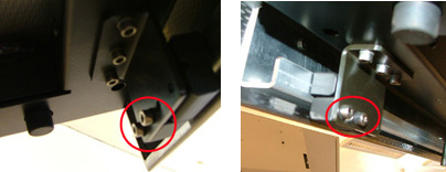
- From the underside of the permanent table, remove the four screws
(two per each side) securing the permanent table to the platesetter
chassis and extract the two permanent table pins (one per each side)
from their housing.
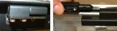
- Install the upgraded permanent table (500-05316A). The shutter pin
has been relocated to center of the permanent table.
Drum registration pins
- Relocate the drum registration pins
to their innermost position on the drum.
- In Service Shell, amend the settings to reflect the drum registration
pins’ new location.
Punch bar registration pins
Relocate
the punch bar registration pins to a position where they are centrally
aligned with the relocated drum registration pins.
Drum fly off brackets and sensors (518-02260A)
- Disconnect the drum fly off sensor connectors.
- Using a hex key, remove the two screws securing each of the left and
right drum fly off brackets and their associated sensors.
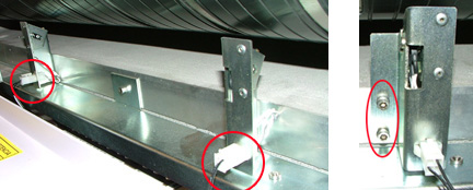
- Install the modified drum flyoff brackets. The modified brackets place
the flyoff detectors closer to one another, and thus they are able to
support 12 in. plates.
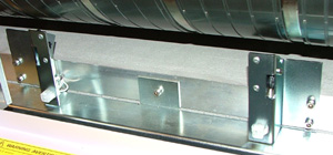
- Install the left drum flyoff bracket (500-04592A) onto the left
side of the platesetter.
- Install the right drum flyoff bracket (500-04594A) onto the right
side of the platesetter.
- Connect the drum fly off sensor connectors to the sensors.
Unloading conveyor (518-02249A)
Platesetters with serial numbers ranging from 300 to 420 inclusive, will
need to have their unloading conveyor (500-02574B) replaced with a later
version of the unloading conveyor (518-02249A).
- Remove the previous version of the unloading conveyor (500-02574B).
- Install the latest unloading conveyor (518-02249A).
Calibrate the platesetter alignment
system
- In the Hardware Tree, locate the Properties: Spring pin motor dialog
box and the Properties: Fix pin motor dialog box and make sure that
the default value of the Max Pos App Value parameter
is set to 468.
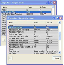
- Type
MAGNUS >> set GC, and ensure the EdgePosMax
parameter’s default value is set to 480000.
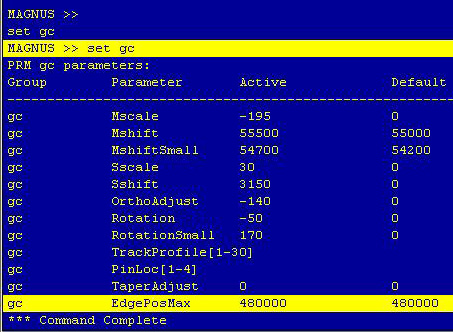
- Calibrating the Magnus 800 alignment system and plate width.
Test the platesetter
Loading/unloading sequence
This platesetter test involves checking the progress of the plate’s
loading/unloading sequence, starting from the autoloader and terminating
at the unloading conveyor.
The test should be performed on a small plate with a dimension of not
less than 12 inches (304 mm).
Note: For an optimum test,
use the supplied 12-inch diameter plates (080-05961).
- Turn on the platesetter and restart Magnus 800 Controller software.
- Turn on the air supply.
- Perform a complete loading and unloading sequence ideally with a 12-inch
plate, and verify the following:
Flyoff sensors
Touch each of the drum flyoff sensors, and in Magnus 800 Controller software,
verify that the status of the sensors changes from Ready to Warning.
|

