Home | Contact Us | Submit Troubleshooting Info | Search | Help
Output | Software Solutions | Proofing | Color, Screening and Calibration | Scanning | Digital Photography | Consumables | POS
Home | Contact Us | Submit Troubleshooting Info | Search | Help
Output | Software Solutions | Proofing | Color, Screening and Calibration | Scanning | Digital Photography | Consumables | POS
Product |
|
|
Kodak® Magnus™ 800 platesetter |
|
Background |
|
|
This procedure describes how to install a variable punch on a Magnus 800 platesetter. |
|
Requirements |
|
|
|
Procedure |
|
|
Workflow Installing the hardware
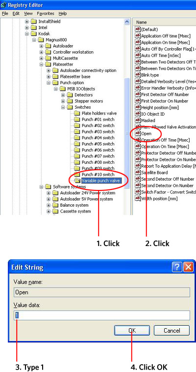
Configuring the softwarePrerequisites
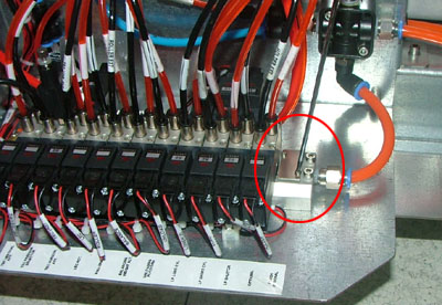
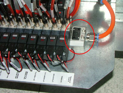
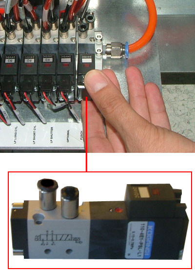
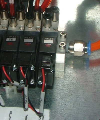
Installing the hardwareInstall the punch solenoid on S300 platesetters Note: For S100 platesetters, continue to the section Route the punch air tubes.
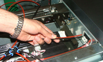
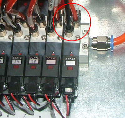
Insert the two air tubes through the access hole located to the right
of the punch bar and route them through the access hole located above
the air tube manifold. At this stage of the procedure, do not cut the
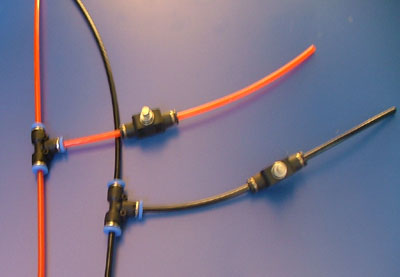
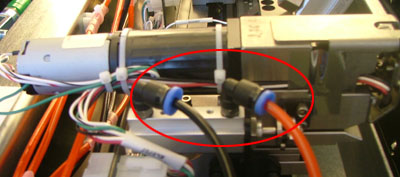
air tubes to their required length, nor secure them to the platesetter. Connect the black air tube to the solenoid’s outer connector and
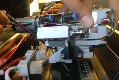
the orange air tube to the solenoid’s inner connector. The punch is secured to the punch bar with a T-nut (372E01011). 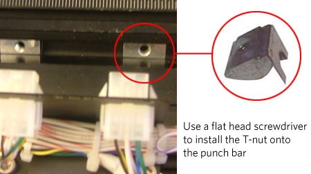
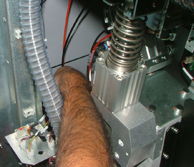
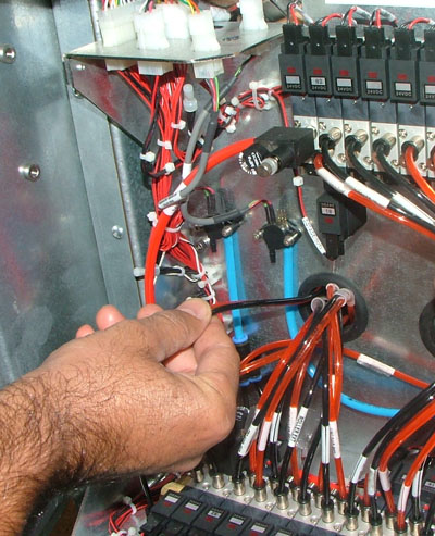
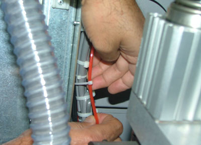
Secure the air tubes to the platesetter Cut the air tubes to their required length and then use cable ties to
secure the tubes to the inside of the platesetter. Begin securing the
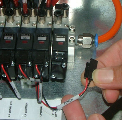
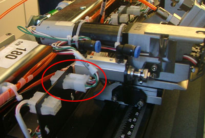
tubes from the punch bar and continue to the air supply manifold. Connect the punch to the power supply Connect the punch’s power supply connector to the closest, available
Molex connector (located on the punch bar). Connect the air tubes to the punch Configuring the software
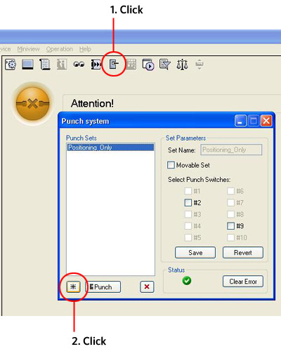
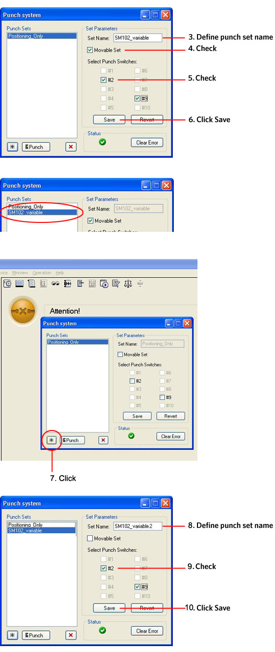
Create two new punch sets for the variable punch
|
|
See also |
|
Technical contact |
Content owner: Meir Dana |
|
Date submitted |
25 Nov 2007 |