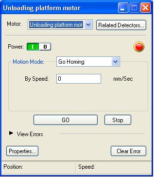
Procedure |
|
Removing the unloading platform belts
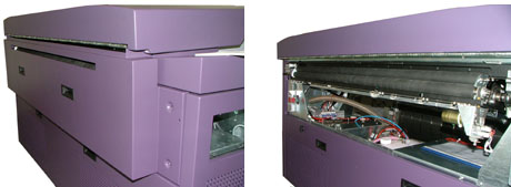
- Remove the platesetter’s upper rear panel:
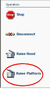
- In Magnus Controller, click Raise Platform to raise
the loading platform:
- Replacing the unloading platform motor on Magnus 800
- Manually raise the unloading platform:
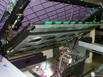
- The unloading platform is supported by two gas springs:
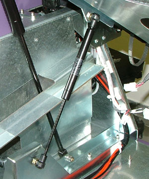
Each gas spring is secured by two black safety clips (one clip is located
at the top of the gas spring and the second clip is located at the bottom
of the gas spring).
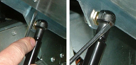
Insert a flat head screwdriver into the safety clips located at the
top of the gas springs and gently pry the clips open. It is not necessary
to remove the clip:
- Once the clips have been opened, carefully extract the upper arms
of the gas springs from their bearings and gently lower the unloading
platform until it rests securely on the chassis.
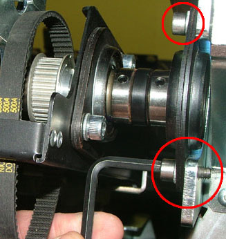
- The unloading platform is connected to the platesetter chassis by
four screws (two on either side of the platesetter).
Use a 5-mm hex key to remove the four screws:
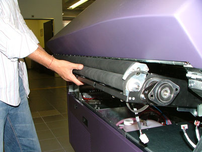
- From the rear of the platesetter, slightly pull out the unloading
platform:
- On both ends of the unloading platform, release the two outer bearing
set screws, and then remove the two outer bearings and their bearing
houses:
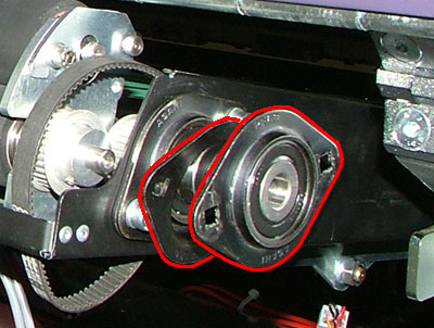
- Pull out the unloading platform and place it on a table:
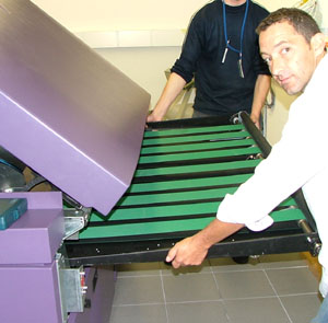
- On both ends of the unloading platform:
- Release the two remaining set screws.
- Remove the two screws securing the inner bearing house to the
unloading platform.
- Remove the inner bearings and their bearing houses:
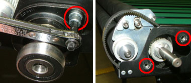
- There are four belt tension assemblies on the unloading platform.
Each assembly is secured to the platform with three screws.
Remove the center screw of each assembly:
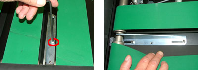
- Release, but do not remove, the remaining two screws on each belt
tension assembly:
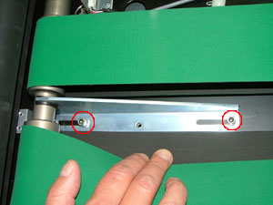
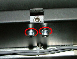
- Each belt assembly is secured to the unloading platform by two screws,
located on the underside of the platform. Release, but do not remove,
the two screws (eight screws in total—two per assembly):
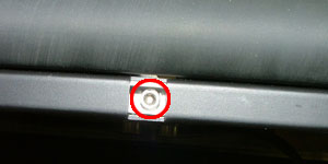
- Four screws are located on the rear edge of the unloading platform.
Release, but do not remove, these four screws.
Note: Release the screws
all the way, without actually removing them:
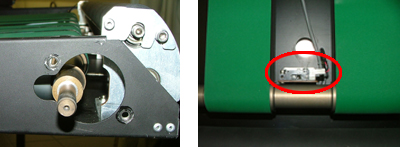
Releasing the four screws alleviates the tension on the unloading platform
belts. The axle can now be moved slightly forward from its bearing.
Important: When moving the
axle, be careful not to damage the unloading platform optical sensor:
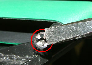
- Locking washers are located on the both ends of the unloading platform’s
front axle. Use a small screwdriver to remove the locking washer located
on the left side of the front axle:
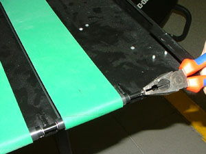
- From the right side of the platesetter, use a pair of pliers to slowly
extract and dismantle the unloading platform’s front axle:
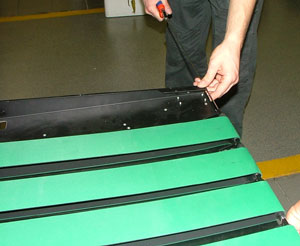
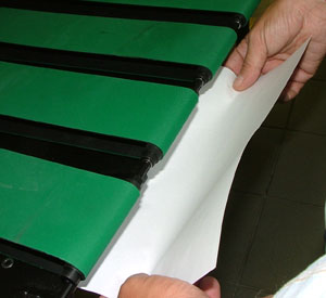
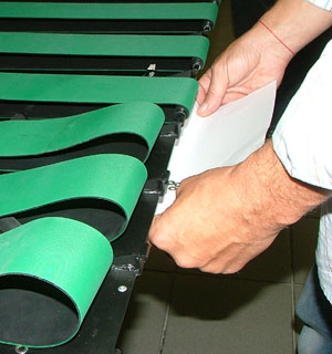
Important: While extracting
the front axle, use a piece of paper to simultaneously collect the washers
that fall off as the axle is dismantled:
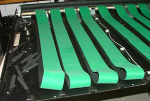
- Remove the black plastic rollers of the dismantled axle and put them
to one side:
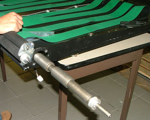
- Remove the unloading platform’s rear axle from it's bearing. Extract
the axle from underneath the belts and pull it through the opening on
the side of the unloading platform:
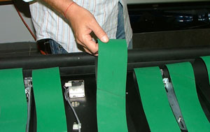
- Remove the defective belt:
Replacing the unloading platform belts
Important: Unless otherwise
stated, coat all screws in Loctite® 242.
- Place the new belt in its correct position on the unloading platform
table. Make sure the arrow on the belt is pointing towards the rear
of the platesetter:

- Insert the unloading platform’s rear axle through the opening
on the side of the unloading platform. (View
image)
- Insert the axle through the belts and place it inside the axle bearing.
- From the right side of the platesetter, insert the unloading platform's
front axle through the belts.
Insert the axle through the individual black plastic rollers (of the
front axle) and use the washers to separate the components:
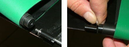
- When the front axle has been reassembled and inserted through all
the belts, place the locking washer on the left side of the platform’s
front axle. (View image)
- Make sure the unloading platform’s rear axle is correctly positioned
inside it’s bearing, and then slowly re-tighten all four screws
located on the rear edge of the unloading platform. (View
image)
Important: Tighten each
of the four screws until the center hole on the corresponding belt assembly
is aligned with the center hole on the unloading platform. (View
image)
- Insert and tighten the three center screws of each belt assembly.
(View image)
- Re-tighten the eight screws securing the belt tension assemblies to
the unloading platform. (View
image)
Note: There are four belt
assemblies—two screws per each assembly.
- Re-tighten the two screws on each belt assembly. (View
image)
- Insert and tighten the center screw of each belt assembly.
(View image)
- On both ends of the unloading platform:
- Install the inner bearings and their bearing houses.
- Insert and tighten the two screws securing the inner bearing houses
to the unloading platform.
- Tighten the bearing set screws.
(View image)
- Reinstall most of the unloading platform back into the platesetter.
Leave enough of the unloading platform protruding so access can still
be gained to the bearings. (View
image)
- On both ends of the unloading platform:
- Install the two outer bearings.
- Install the two outer bearing houses.
(View image)
- Reinsert the entire unloading platform back into the platesetter.
- Use a 5-mm hex key to install and tighten the four screws connecting
the unloading platform to the platesetter chassis. (View
image)
- Tighten the two outer bearing set screws.
- Manually raise the unloading platform and insert the gas springs inside
the gas spring bearings. (View
image)
- Secure the gas springs to their hinges by closing the two black safety
clips. (View image)
- Manually close the unloading platform.
- Replacing the unloading platform motor on Magnus 800
|