Home | Contact Us | Submit Troubleshooting Info | Search | Help
Output | Software Solutions | Proofing | Color, Screening and Calibration | Scanning | Digital Photography | Consumables | POS
Home | Contact Us | Submit Troubleshooting Info | Search | Help
Output | Software Solutions | Proofing | Color, Screening and Calibration | Scanning | Digital Photography | Consumables | POS
Objectives:
Before installing the SCU:
 Park the picker in the middle of the table.
Check that the table fixture (#92-0369) is attached and level.
Remove both side panels from the garage.
Move the garage into position.
- Roll the garage on dollies near its permanent location.
- With a helper, lift one end of the garage off the crate bottom at a time. Slide it off the edge and onto the floor.
- Slide the garage towards the Trendsetter VLF.
- Put a 1" wood block under each arm of the floor plate to lift it up.
- Slide the garage plate under the floor plate.
- Remove the wood blocks.
- Align the holes in the garage plate with the holes in the floor plate
- Install the fasteners loosely.
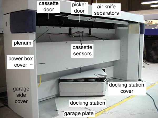
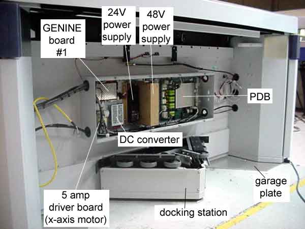
Garage components Garage power box
Level the garage.
- Use a calibrated digital spirit level to check that the garage face is level (plumb) to 90° ±0.2°.
To adjust the garage level:
- Rotate the adjustable garage feet until the desired angle is achieved.
- Tighten the fasteners.
Check the distance from the plenum to the table edge at the front and
back. It should be 660mm ±5mm.
- Bump the garage until the distance at the front of the machine and the back are more or less equal.
Note: Don't push the garage from the top. Sit down and kick the bottom to move the garage into place.
Check that the plenum is aligned to the system centerline laser.
- Turn the laser plane ON.
- Check that the laser plane is aligned to the reference marks. The laser should touch both edges of the plenum centerline feature.
- Bump the garage until the laser is within the plenum centerline feature.
Note: Don't push the garage from the top. Sit down and kick the bottom to move the garage into place.
Prepare for cassette alignment.
- Turn the AL air supply OFF.
- Remove the kick panels from the Trendsetter VLF.
- Remove the plug from the garage air supply fitting.
- Connect the airline from the garage to the Trendsetter VLF.
- Connect the electrical cables from the garage to the VLF Trendsetter.
- Turn the AL air supply ON.
- Remove the docking station cover.
- Open the cassette and picker doors manually. Prop them open with a foam pad at each end of the plenum.
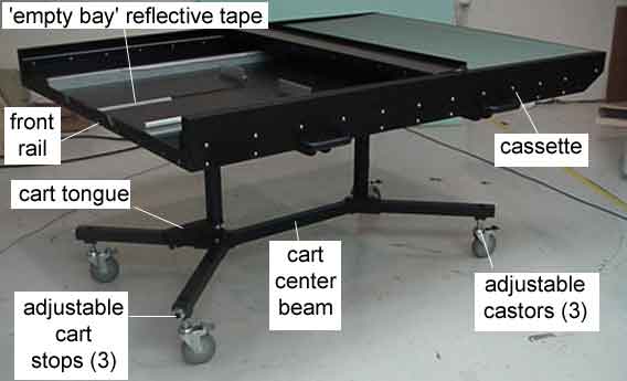
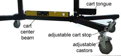
- Check that the adjustable cart stops on the cassette cart (just above the front wheels) are loose.
- Roll the cassette cart into position inside the garage.
- Check that the cassette centerline is aligned with the system centerline laser. Use the center of the strip of black tape that runs along the cassette bottom as a reference point.
- Attach the two plenum fixtures (#92-0392) by slipping them onto the front rail of the cassette cart, one at each end, and sliding them over the plenum. The fixtures should hold the cassette tightly to the plenum.
- Insert the sensor end of the cassette alignment fixture (#92-0370) through the garage doors and place it onto the cassette, being careful not to damage the sensors.
- Place the other end against the table fixture and align the brackets.
- Insert both quick-release pins.
- Connect the sensor readout box to the cassette alignment fixture via the serial cable (#16-3500).
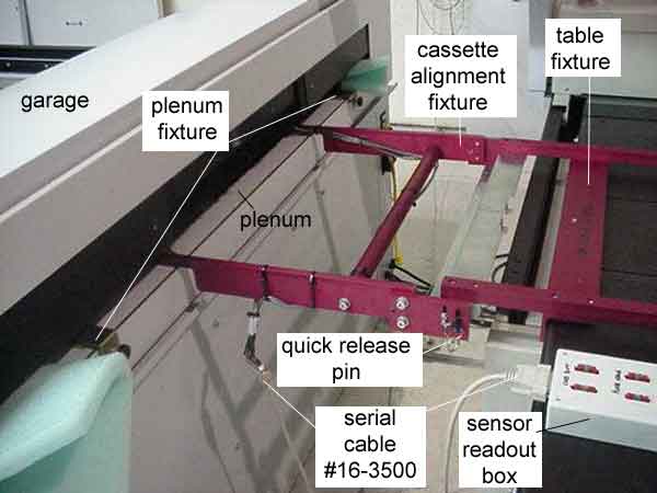
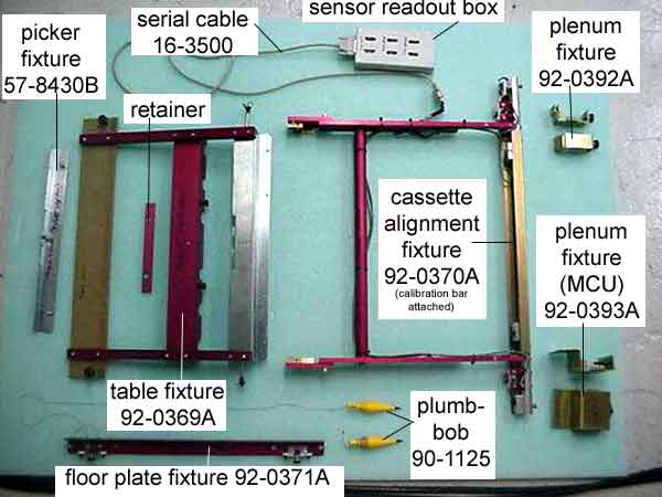
SCU alignment fixtures Fixture detail
Check the distance from the table edge to the inside edge of the
cassette.
- Turn ON the sensor readout.
- Check that both Plate Edge sensors are green.
- Bump the garage either away from the table or toward it, as required, until both lights are green.
Note: Don't push the garage from the top. Sit down and kick the bottom to move the garage into place.- Recheck the centerline alignment.
- Securely tighten the garage plate to the floor plate.
- Recheck the plenum distance (Step 6) and the centerline alignment (Step 7).
Check the height from the plenum to the picker.
- Move the picker into the pick position (carriage at the end of the track, picker head inside the garage).
- Check that both Pick Height sensor readouts are green.
- Loosen the screws inside the garage side pods, at the bottom.
- Rotate the 4 vertical adjustment screws until both Pick Height sensor readouts are green.
- Recheck that the Plate Edge sensor readouts are still green.
- Tighten all the fasteners inside both garage side pods.
Check the height from the cassette to the picker.
- Check that both Cass Bott sensor readouts are green.
- Loosen the large lock nuts on top of the adjustable cassette castors (the two closest to the garage)
- Rotate the adjustable cassette castors until both Cass Bott sensor readouts are green.
- Retighten both large lock nuts.
- Recheck that the Plate Edge and Pick Height sensor readouts are still green.
Check that the cart is level along the center beam. It should be 0°
±0.2°.
- Place the calibrated digital spirit level along the cart's center beam. Take a reading.
- Loosen the large lock nuts on top of the adjustable cassette castors (the two furthest from the garage)
- Rotate the adjustable cassette castors until the cart is level.
- Retighten both large lock nuts.
Align the docking station to the cassette cart.
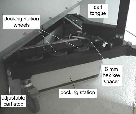
- Slide the docking station into the "V" of the cart rails. The cart rails should contact at least one wheel on each side of the docking station.
- Place a 6mm hex key on top of the docking station, directly under the cart tongue (the bar that extends past the front frame of the cart).
- Lower the cart tongue evenly onto the hex key.
- Tighten the cart tongue fasteners.
- Remove the 6mm hex key
- Activate the "cass lock" actuator in the side of the garage.
The cart rails should still be contacting the wheels on the docking station.- Tighten the docking station to the garage plate.
- Rotate the adjustable cart stops out until they contact the docking station.
- Deactivate the "cass lock" actuator.
- Remove the two cassette-to-plenum fixtures.
- Reactivate the "cass lock" actuator in the side of the garage.
Check that the sensor readouts are still green. Adjust if needed.- Deactivate the "cass lock" actuator.
Aligning docking station to cart
Adjust the cart stops.
- Move the picker over the table.
- Remove the cassette alignment fixture.
- Remove the foam pads propping the garage doors open.
- Remove the table fixture.
- Roll the cassette cart out of the garage.
- Rotate the adjustable cart stops out 1/4 of a rotation.
- Securely tighten the lock nuts.
- Clean the cassette before loading plates.
Connect the garage power cable to the AC power.WARNING! Make sure that both power switches on the SCU are OFF.
Check the AC power at the customer-supplied receptacle.
It must be correctly wired and on the same AC panel as the AC receptacle for the workstation. See the Site Preparations & Requirements document for more information.
Install both side covers on the garage.