Home | Contact Us | Submit Troubleshooting Info | Search | Help
Output | Software Solutions | Proofing | Color, Screening and Calibration | Scanning | Digital Photography | Consumables | POS
Home | Contact Us | Submit Troubleshooting Info | Search | Help
Output | Software Solutions | Proofing | Color, Screening and Calibration | Scanning | Digital Photography | Consumables | POS
Before installing the MCU:
 Roll the MCU into its final position.
Check that the plenum of the MCU is aligned to the system centerline
laser.
- Turn ON the laser plane
- Check that the laser plane is aligned to the reference marks. The laser should touch both edges of the plenum centerline feature.
To adjust the alignment of the MCU:
- roll the MCU until the plenum feature is aligned to the system centerline laser.
Check the distance from the table edge to the plenum.
- Open the picker door manually and use foam blocks to keep it open.
- Measure from the inside edge of the plenum to the edge of the table, using a measuring tape. Check the distance at two points on the table, front and rear. The distance should be 660mm at each point.
- Roll the MCU until the distance is 660 mm at both points.
- Recheck the system centerline alignment.
Remove the castors.
- Carefully slide the chariot until it is fully open. You must support the chariot as you open it, as the wheels will not touch the ground.
- Remove the large rear access panel and place it safely out of the way.
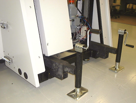
- Attach the two rear lifting fixtures (#92-0376A) to the lower rear frame.
Rear lifting fixtures
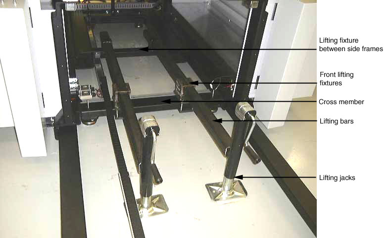
- Attach the two front lifting fixtures (#92-0377A) to the front cross member.
- Place the longer front fixture (#92-0374A) between the side frames.
- Slide the lifting bars (#56-3266A) through the front lifting fixtures and into the other front fixture.
- Insert the four lifting jacks (#92-0084A) into the 4 lifting fixtures.
Front lifting fixtures
- Place two white plastic slide plates (#57-8573A) under each jack.
- Carefully raise the jacks until all four are loaded. Continue to raise the jacks until the castors are 20mm above the floor.
- Place wood safety blocks (#59-3808) under each corner of the MCU.
- Remove the four screws holding the castors onto the MCU, using a ratchet handle, 450mm (18") extension and a 8mm hex key socket.
- Lay on the floor beside the MCU and reach underneath to remove the castors.
- Keep the castors and fasteners on site for future moves.
- Lower the MCU until it rests on the four outside feet.
- Do not remove the lifting jacks yet.
Check that the base of the MCU is level to 0° ± 0.2°.
- With the chariot open, crawl inside the MCU.
- Place a calibrated digital level along the rear cross member and then the side frame rails.
- Place the level on the inside edge of the plenum. It is important that the plenum and the side frame have the same reading.
- rotate the adjustable feet until the desired angle is achieved.
Attach the two plenum fixtures (#92-0393A) to the plenum (put tape on
the plenum to prevent scratching the surface). The distance from the
outside edge of the cassette door opening to the outer edge of each
fixture is ± 320 mm (12.5").
Attach the cassette alignment fixture (#92-0370A).
- Connect the sensor tester.
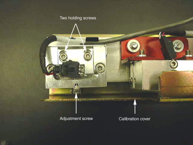
- Turn the power ON. All lights should be green. To adjust any sensors, loosen the two screws holding the sensor in place and use the adjusting screw to make any adjustments. Tighten the screws when done.
Calibrating the sensors
- Remove the calibration cover (the front brass cover).
Check the position of the MCU. To adjust the position
of the MCU:
Check the height from the plenum to the picker. To adjust the height
of the plenum:
Remove the following items and pack them back into the installation
toolbox:
Remove the foam pads from the cassette door opening.
Lower the other two MCU feet inside the MCU.
Check the operation of the chariot. It should roll easily and should
engage the MCU easily. To adjust the chariot
ride height:
Re-install the black safety guard in the MCU.
Connect the air and power lines.Do not install the cassettes yet! Complete the rest of the Autoloader installation before loading the cassettes into the MCU.
Install the guard rail
Install the L-Conveyor or Straight
Conveyor
Install the SSR
When the Autoloader is fully installed, follow these steps to install each cassette:
- Turn the compressed air and power ON.
- Open the chariot until it stops.
- With 3 helpers, lift one cassette over the chariot.
- Lower the rear edge of the cassette into the MCU until the front edge clears the chariot body.
- Position the cassette on the rollers.
- Push the cassette into the MCU until the latch engages (an audible double-latch).
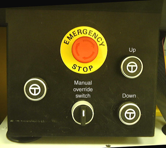
- Manually raise or lower the cassette until the next bay is in position. Turn the manual override switch to the left and use the up and down buttons to position the cassette bays.
MCU manual operation
- Repeat the procedure for the other cassettes.
- Close the chariot door.