Home | Contact Us | Submit Troubleshooting Info | Search | Help
Output | Software Solutions | Proofing | Color, Screening and Calibration | Scanning | Digital Photography | Consumables | POS
Home | Contact Us | Submit Troubleshooting Info | Search | Help
Output | Software Solutions | Proofing | Color, Screening and Calibration | Scanning | Digital Photography | Consumables | POS
Before installing the Slipsheet Removal System:
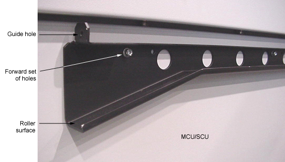
 Install the roller bracket on the MCU/SCU.
- Position the roller bracket so that the angled edge is facing downward and use five M5 screws to secure the bracket against the side of the MCU/SCU. Use the forward set of holes on the bracket as shown below.
Installing the cassette side roller bracket
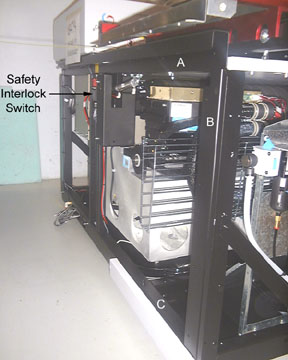
Before installing the roller bracket assembly on the Trendsetter VLF,
the safety interlock switch cable may need to be rerouted so that it is
not damaged by the roller bracket assembly in step 3.
- If the cable is routed inside the channel marked 'A' in the photo below, disconnect the cable from channel 'A', reroute it down channel 'B', along channel 'C', and up to the safety interlock switch (remove all cable ties from channel 'A'.)
Routing the safety interlock switch cable
Install the roller bracket on the Trendsetter VLF.
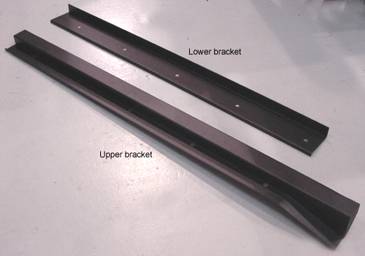
- This bracket consists of two parts that are 'clamped' together around the VLF TS frame: The lower bracket and the upper bracket.
Trendsetter side roller brackets
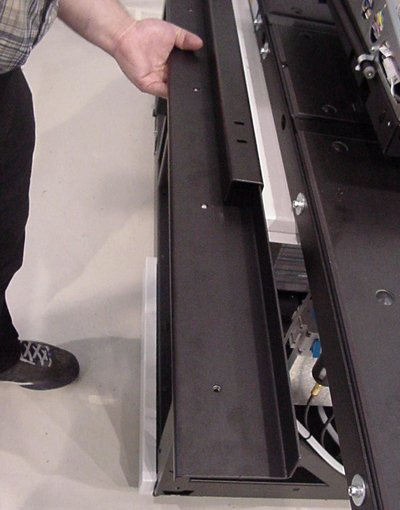
- Slide the longer edge of the lower bracket in under the frame of the VLF TS.
Installing the Trendsetter side roller brackets
- The 'U' shaped part of the upper bracket fits over the VLF TS frame and rests on the lower bracket - the wide opening faces forward to receive the SSR roller.
- Insert the five M6x12 screws and Bellville washers holding the two brackets together but do not tighten them - the bracket assembly must be able to slide for adjustment (when the two brackets are pulled together they are held in place by sandwiching the frame of the VLF TS.)
- Push the roller bracket as far back as possible. Do not tighten the screws yet.
Installing the SSR ramp brackets for MCU configurations.
To prevent the SSRs wheels from damaging cables and hoses that are connected to the left side of the VLF TS, a ramp is installed that lifts the SSR up so as to miss the cables and hoses.
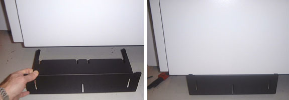
- Attach the small bracket shown below to the front lower corner of the MCU facing the VLF TS. The bracket is held in place by two screws on the underside of the MCU - loosen, do not remove, the two screws and slide the bracket in place.
Installing the lower ramp brackets
- Tighten the two screws.
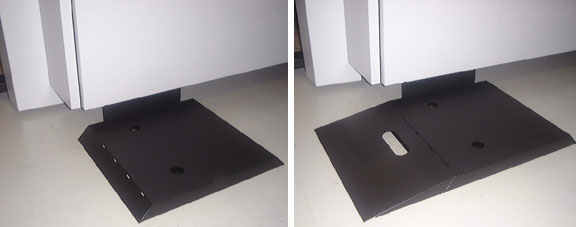
- Attach the large part of the ramp assembly to the bracket just installed. The three bolts protruding from the side go through the three slots seen above.
- The last, detachable part of the ramp hooks into place at the front of the VLF TS by the tongues and grooves provided on the ramp parts.
Installing the upper part of the ramp
Installing the SSR unit
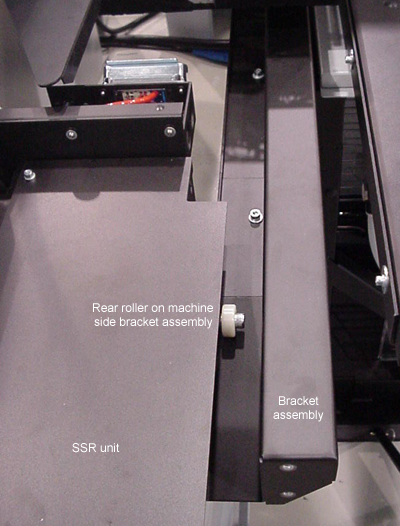
- From the front of the machine, align the SSR unit rollers with the brackets just installed. Roll the SSR onto the ramp until the rear rollers are running on the brackets. The photo below shows the VLF TS-side roller.
Rolling the SSR onto the roller brackets
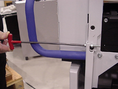
- On the MCU/SCU side of the SSR there is a guide screw, M6, that must be guided into the guide hole in the MCU/SCU bracket - See photo in step 1. Use a T-handle Allen key to align the guide screw while pushing the SSR unit into place.
Guiding the guide screw into its hole
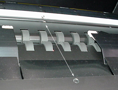
- Push the SSR until the rear VLF TS-side roller actually rolls off the end of the bracket - the SSR will now be supported by two rollers on the MCU/SCU side and one roller on the VLF TS side. The SSR should stop against the roller brackets (make sure that it does not stop against the VLF TS side bracket before the MCU/SCU bracket.) The SSR is in the correct position when the center screw on the top of the SSR and the screw on the MCU/SCU are aligned. Check the alignment using the laser beam on the center screw
Correct SSR alignment
- Slide the VLF TS side roller bracket forwards until it touches the SSR. This will help to align the SSR if it is removed and installed again.
- Tighten the five screws of the roller bracket assembly.
Connect umbilical to the SSR
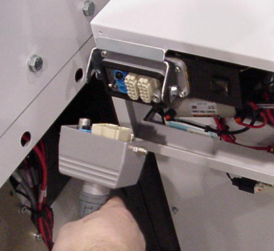
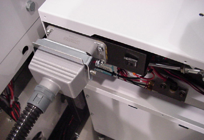
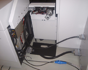
- Connect the umbilical cable between the MCU/SCU and the SSR. To lock the plug in place, pull the lever backwards (away from the SSR.) The umbilical supplies both power and air to the SSR.
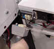
Connecting the umbilical cable
Install the slip sheet bag in the SSR.
Remove the detachable ramp and store it at the back of the SSR on the
floor.Storing the SSR ramp