

Home | Contact Us | Submit Troubleshooting Info | Search | Help
Output | Software Solutions | Proofing | Color, Screening and Calibration | Scanning | Digital Photography | Consumables | POS
Home | Contact Us | Submit Troubleshooting Info | Search | Help
Output | Software Solutions | Proofing | Color, Screening and Calibration | Scanning | Digital Photography | Consumables | POS
Dolev 800/800V/800V² TIC - Installation
Punch/On-Line Conveyor
General
See FCO17436 - 05/05/93 Light Area Harness
See FCO 17851 - 15-JUN-93 Manifold installation
See FSB 378 - 19-JAN- 94 Changes on Punch units
See FCO 18908 - 09-Mar-94 Punch Basket Big R
Overview
Punch Types 1 and 2
Punch System
Design and Operation
Scitex offers a leading edge, customer-defined punch system for the Dolev 800 Imagesetter. The punch system is used by printers to eliminate the need for mounting film to carrier sheets, manual registration and punching. A maximum of 10 punch assemblies can be installed in the film width direction, on the right flange of the Imagesetter drum.
To assist CreoScitex and the customer in the punch system definition, a special form has been prepared. The customer and CreoScitex engineer should complete all requested values on this form. STCL then prepares a confirmation drawing for customer approval. This drawing, a sample of which appears in Appendix A, is used by the CreoScitex engineer to actually install the punch system.
Although filling in the punch definition form is not a pre-requisite for ordering a punch system, the system can not be installed without the customer-approved confirmation drawing supplied by STCL. Since numerous configurations are available and some restrictions exist (such as minimum hole distances, hole size, and hole placement relative to the exposed area), STCL assists in the punch system definition. This ensures that all details regarding the customer's punch system will be transmitted to the local CreoScitex experts.
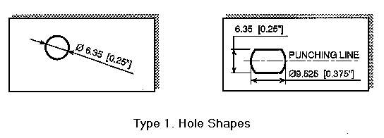
CreoScitex divides its punches into two types:
| Type 1 | Punch assemblies of
this type are available from stock. Two different hole shapes are available: 6.35 mm round
and 6.35 x 9.525 mm oval. Additional Type 1 hole shapes may be made available in the future. |
| Type 2 | Punch
assemblies of this type are manufactured according to customer definition
of hole dimensions. CreoScitex does not encourage this type of punch, since
it requires a added logistic process which generally takes a long time to
complete. The final punch assembly is exactly the same as for Type 1 punches.
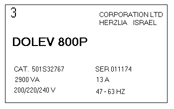
Installation is also the same. Until December 1992, CreoScitex manufactured Dolev 800 Imagesetters without punch compatibility. Subsequent to that date, all Dolev 800 Imagesetters are punch compatible. Punch-compatible Imagesetters are labeled Dolev 800P, instead of Dolev 800, on their manufacturing information plates (located at the lower right back side of the Imagesetter). Note that the logo on the front panel remains the same. |
Overview
The Punch Sequence
Punch System Controls
Punch Control Logic
Compressed Air
Flow Adjustments
Punch Assembly Structure
Punch Sub-Types
The Dolev 800 punch system concept is to punch every hole via an independent assembly. Since film is loaded into the drum without using a tightly restricted path, the punch "jaws" must be well out of the film path during loading. Once film is secured to the drum with the roller and the vacuum, the punch jaws move into place, punch the film, and return to their "out" position. Note that very accurate punch positioning repeatability is required. Accuracy in punch positioning is achieved by using a small preloaded miniature linear bearing and by attaching together two hardened mounting surfaces, one round and one plane.
The moving part of the punch assembly is the unit. It can be either at the "out" position or at the "in" (punching) position. The moveable cutting blade of the punch is the rod. Like the unit, it can be either at the out or in positions. Both rod and the unit are activated by air cylinders. There are two double-action air cylinders (not spring-activated) per punch assembly. The punch system therefore requires a continuous, external air pressure supply for operation.
An additional operation of every punch assembly is ejecting spent film slugs from the system. Three blasts of compressed air are used to achieve this. This operation is performed following the film punch, and before moving the punch rod to its out position. Film slugs are collected into a large black hose, located near the unloading cassette. The user must empty this hose of spent slugs two to four times per month.
The following describes a typical punching sequence:
1. Unit in Brings the unit into punching position
2. One second delay Allows pressure stabilization
3. Rod in Executes film punch
4. One second delay Allows pressure stabilization
5. Three blasts of air Removes spent film slugs
6. One second delay Releases pressure completely
7. Rod out Returns to its out position
8. One second delay Allows pressure stabilization
9. Unit out Returns the unit to its out position
To perform the punching sequence, the system uses three 12-volt DC valves and, for each punch assembly, three limit switches (a type used widely in the Dolev 800).
| The three valves are: | Unit In/Out Valve Rod In/Out Valve Slug Out On/Off Valve |
| The three
photo-interrupter indications are: |
Unit In Unit Out Rod Out |
Note: 1.The unit in/out and the rod in/out valves are of the same type. The slug out on/off valve is bigger. 2.No pressure level sensor exists. 3.The "rod in" position is detected as "no rod out" state. 4. There is no slug out on/off indication.
Each punch assembly therefore requires five separate air tubes for operation, labeled as:
Unit In
Unit Out
Punch Rod In
Punch Rod Out
Slug
Additionally, one large tube is required to bring the spent film slugs into the collecting hose.
All punch assemblies are operated in parallel. For example, the "unit in" air tube activates all units. All photo-interrupter readings are performed in parallel, causing the system to wait until the last photo-interrupter reading is correct before performing the next step in the sequence.
Note: 1. At least one punch assembly must be fully connected in order for all punch assemblies to operate. 2. The Imagesetter cannot discern how many punch assemblies are installed. 3. To release the Imagesetter from an error condition, you must restart the Imagesetter.
Compressed Air Flow Adjustments
Since the punch assemblies move independently, they operate at different speeds. One of the final adjustments required is to minimize operating speed differences by adjusting the four air flow controllers on each punch assembly. In most cases, only a few adjustments are necessary.
| Refer to: | Dolev 800 Right Punch
Assembly, Drawing No. 731D8A941 Dolev 800 Left Punch Assembly, Drawing No. 731D8F310 |
Numbers appearing below inside square brackets ([ ]) refer to drawing callouts.
Each punch assembly is comprised of two main elements:
1. Stationary element, including:
a. Base for punch [25]
b. Rail [5]
c. Flow controllers (2 pieces) [10, 13]
d. Long stroke air cylinder
("Humphrey") [9]
e. Sensors plate (including 2
photo-interrupters and harness) [1]
f. Stopper plate (including
hardened bushing) [35, 36]
2. Moving element, including:
a. Punch block and rod [18]
b. Short stroke pancake cylinder
("Bimba") [26]
c. Sensor plate for punch
(including 1 photo-interrupter) [11]
d. Flow controller (2 pieces and
tubes) [13]
e. Rail sliding unit [5]
f. Bracket [27]
g. Adjustment screw (including hardened
ball) [29]
h. Mouth [33]
i. Slug tube
j. Cover for punch [24]