Home | Contact Us | Submit Troubleshooting Info | Search | Help


    Output | Software Solutions | Proofing | Color, Screening and Calibration | Scanning | Digital Photography | Consumables | POS


Delay calibration test for ThermoFlex Mid and Narrow


Product

 
  • ThermoFlex® Mid
  • ThermoFlex Narrow

Background


The objective of performing a delay test is to calibrate the delay parameter for the Data Distribution Board (DDB), so that the exposed horizontal lines are perfectly straight. The plate is exposed at a resolution of 100 dpm, in different delay values. The optimal delay value is the delay value of the best exposure. ThermoFlex Controller automatically calculates the optimal delay values for other resolutions.

Note: Test results do not depend on the plate type or size, so this test can be performed on any plate type that the customer uses.

Note: When defining media, if you do not enter the correct media thickness, delay problems will appear on the actual job.


Requirements


Procedure


This procedure contains two stages:

Testing delay
  1. Load a test plate.
  2. Load a plate.
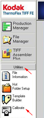
  3. In TIFF FE, from the Launch Pad, select Utilities > Calibrate.
  4. In the Calibration Type box, select Delay.


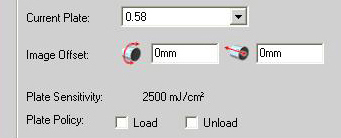
  5. In the Current Plate list, select the Plate that you are using.


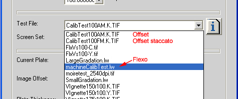
  6. Select the relevant test file according to the type of plate:
    • Flexo—select machineCalibTest.lw
    • Offset—select CalibTest100AM.K.TIF
    • Offset Staccato—select CalibTest100FM.K.TIF


Note:
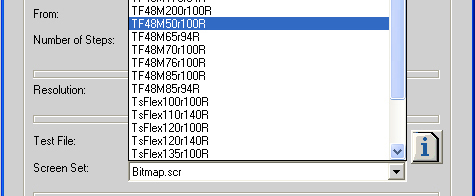
If your plate type is Flexo, you must also select the relevant screenset. For example:


  1. Define the Image offset values:
    • Horizontal offset—The value around the drum in mm
    • Vertical offset—The value along the drum in mm
    If you use the same plate for several tests, define different offset values for each test.
    Note: The (0,0) offset coordinate is located at the upper-left corner of the plate.
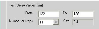
  2. In the Test Delay Value area, type the values for the delay range.
    For coarse delay calibration, the recommended range is:
    • For Flexo plates using a 1:2 lens: 122–126
    • For Flexo or Offset plates using a 1:3 lens: 80.5–84.5


  3. In the Number of steps list, type the required number of exposures for the delay range. The recommended number of steps is 11.
  4. Click Test to initiate the delay test according to the settings. The application performs several exposures.
  5. Select the best result and run a fine-tuning test in a range of ±1, using 11 steps.
    Note: After you perform the coarse test, you may need to calibrate resolution before performing the fine test. Vertical artifacts indicate that the resolution motor step is out of range.
  6. Select the best results and run the test in a range of ±0.1, using 11 steps.
  7. Repeat step 12 in a range of ±0.05.

Selecting the correct delay

  1. Develop the plate.
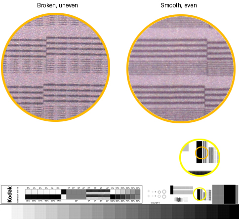
  2. In the section of the test file shown following, examine the results with a microscope . A bad delay value results in a jagged effect on the horizontal line.
    • Broken, uneven lines indicate a delay problem.
    • Smooth, even lines indicate correct delay.
  1. In the Delay Value box, type the optimal delay value.
  2. Click Save. The optimal delay value is transfered to Lotem Controller. Lotem Controller automatically calculates the optimal delay values for other resolutions.

Technical contact(s)
 

Content owner: Viki Arviv
See the Escalation page for escalation contacts.

Date submitted
 

22 Jun 2004


    Copyright © 2005 Creo Inc. All rights reserved. Confidential. Back to top.