| |
This procedure includes the following sections:
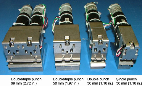
Installing punches
- In the center of the punch beam, locate the spare T nut, and then
proceed to step 4.
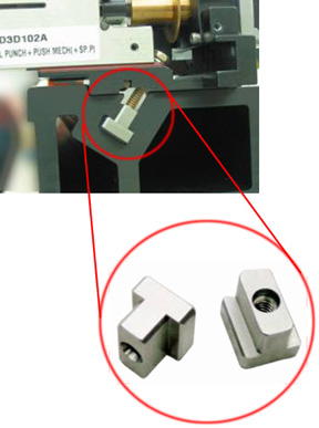
- If a spare T nut is not available in the center of the punch beam,
mark the location of each of the existing punches.
- Remove the two punches on the left side of the middle punch, and remove
the middle punch.
- Insert a T nut into the groove, and slide it to the
middle of the punch beam where the new punch will be installed.
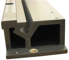
- On the punch beam, install the punch according to the customer's punch
configuration, and tighten the hex screws into the locking nut.
Note: Use the customer's punched reference plate, emulsion side
up, to determine the correct punch positions.

- Connect the punch connector to the punch Molex® connector.

- Make any final adjustments to the punch system after you assemble
the platesetter.
(Optional) Changing the location of the detector wiring
Note: When two punches are positioned too close to each other, you
need to change the location of the punch detector wiring before
adjusting the punch detector.

- Disconnect the Molex connector with the punch detector wiring from
the punch detector.
- On the punch, remove the two #3 screws that help secure the detector
holder to the punch, and set the screws aside.

- Remove the two #2 screws that help secure the detector holder to the
punch, and set the screws aside.
- Turn the punch detector upside down, and reconnect the Molex connector
and wiring to the punch detector.

- Insert and tighten the two #2 screws.
- Insert and tighten the two #3 screws.
- (Optional) On the side of the punch, place a sticker over the exposed
wires so that they do not interfere with the smooth operation of the
punches.
Defining punches
The MCU II accommodates up to six punches, including the center punch.
The number of punches that you need to define depends on the customer's
configuration.
Note: In some cases, the platesetter is delivered with the punch
system installed. If your platesetter is delivered with the punch system
installed, proceed to Testing the defined punches.
- Start the Magnus 400 Controller software, click anywhere in the workspace,
and press Ctrl+U to enter Expert mode.
- In the Magnus 400 Controller software, select Utilities > Hardware
> Others. Right-click Magnus400, and select Properties.
- In the Properties: Magnus400 dialog box, double-click +IO OBJECTS.
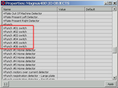
- In the Properties: Magnus400\IO OBJECTS dialog box, double-click each
punch that is defined in the customer's configuration, and then double-click
the Open parameter for the defined switch.
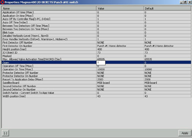
- Change the value of the Open parameter to 1, and click
Apply.
- For your changes to take effect, restart the Magnus 400 Controller
software.
Defining a custom punch system in the database
- In the Magnus 400 Controller software, select Utilities > Hardware
> Database, and double-click Punch.
- In the Punch Data Base dialog box, select the check box next to each
punch that you want to include in the customer punch system, and then
select the punch set name that you want to use for the custom punch
set.
Note: You can add new punch set names, as required—for example,
to define a specific set of customer punches or for a specific customer
configuration.
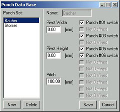
- Click Save.
Testing the defined punches
- In the Magnus 400 controller software, open all the punches that you
defined in the system and their corresponding punch detector dialog
boxes:
- For the punches, select Utilities > Hardware > Punch
Conveyor System > Punch System > Punch System Switches,
and open the first punch switch that is defined in the system—for
example, Punch #01 switch.

- For the punch detectors, select Utilities > Hardware >
Punch Conveyor System > Punch System > Punch System Detectors,
and open the relevant punch detector—for example, Punch #1
Home detector.
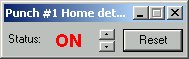
- In the Punch switch dialog box, click Start.
The status in the Punch detector dialog box should change from ON
to OFF and back to ON. This indicates that the punch
home position is working correctly. If not, see (Optional)
Adjusting a Punch Detector.
- Repeat steps 1 and 2 for each punch defined in the system.
(Optional) Adjusting a Punch Detector
Important: When adjusting a punch detector, do not touch the two
#3 screws.
- On the punch, loosen the two #2 screws.
- In the Magnus 400 Controller software, select Utilities > Hardware
> Punch System > Punch Motors. Double-click the relevant punch
motor, and click Start.

- Rotate screw #1 clockwise, until the punch motor is running smoothly
without interruption, and then rotate the screw counterclockwise, until
the punch motor stops.
- After the motor stops, thoroughly rotate screw #1 counterclockwise
another one-and-a-half rotations.
- Tighten the two #2 screws.
- Activate the punch, and verify that it is working properly. Make sure
that the punch rod is not blocking the punch plate slot.
Fine-tuning the distance between punches
Note: Always use the zero mark on the punch beam as your reference
point when performing the fine adjustment.
- Load a plate and perform punch.
- Adjust the final punch positions according to the punch results.
|