Home | Contact Us | Submit Troubleshooting Info | Search | Help


    Output | Software Solutions | Proofing | Color, Screening and Calibration | Scanning | Digital Photography | Consumables | POS


Thermal Head 2.0 Installation

Steps 11-14: Connect the Cables and Hoses

Print version:  To print out the instructions below, click on the print icon at the top of the page.
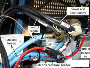

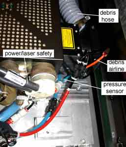
Attach the cables - side view
[details]

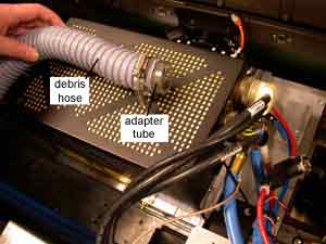
Attach the cables - rear view
     

Insert the adapter tube into the debris vacuum hose
[details]

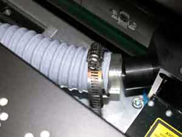
Connect the debris vacuum hose to the nozzle and secure it with a hose clamp
[details]
     

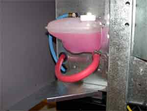
Add coolant to the reservoir to the required level
[details]


Details - Connect the Cables and Hoses

  1. Attach the following cables and hoses, as shown in the photos above:
    1. Route the red ¼" airline and the pressure sensor cable through the cable track in the output device.
    2. Install the pressure regulator with built in gauge in the ¼" red hose before or after the cable track.
    3. Note:  The pressure regulator is directional. Please ensure the arrow on the regulator points in the direction of the airflow.

    4. Trim the ¼" red hose with scissors if required.
    5. Plug the air hose from the device into the barb fitting in the airline that leads to the pressure regulator.
    6. Turn on the air jet. Set the pressure regulator to the pressure (psi) indicated on the label on the side of the pressure regulator. If there is another flow control valve on this air hose, such as a needle valve at the pneumatic manifold, this should be set and remain fully open before setting the nozzle's pressure regulator.
    7. Inspect the o-rings on the fittings of the two coolant hoses. If there are any nicks or other damage, replace the o-rings (59-3415) to prevent leaking. They can be replaced with a standard Buna-N size o11 o-ring, available from any industrial supplier or from Creo.
    8. Connect the two coolant hoses.
    9. Note:  The direction of coolant flow through the head is not important.
    10. Check that all connectors are fully inserted and latched.
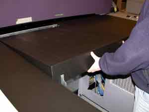
    11. Replace the table center panel [photo], and then the head access panel [photo].

  2. Insert the adapter tube into the debris vacuum hose.
  3. Connect the debris vacuum hose to the nozzle and secure it with a hose clamp.
  4. Add coolant to the reservoir to the required level.


    Copyright © 2005 Creo Inc. All rights reserved. Confidential. Back to top.