Home | Contact Us | Submit Troubleshooting Info | Search | Help
Output | Software Solutions | Proofing | Color, Screening and Calibration | Scanning | Digital Photography | Consumables | POS
Home | Contact Us | Submit Troubleshooting Info | Search | Help
Output | Software Solutions | Proofing | Color, Screening and Calibration | Scanning | Digital Photography | Consumables | POS
To print out the PM instructions below, click on the print icon  at the top of the page.
Before going to the site:
Objectives: Check safety first! Determine that all Magnus VLF components are safe to operate and to work on. Walk around the entire device to examine the exterior and surroundings for damage and any issues that may require further investigation or repair.
| Safety and Exterior Evaluation | What to Do | What to Look For | Procedure
Parts |
|---|---|---|---|
| Semi-Automatic (SA), ContinuousLoad (CL), Multi-Cassette Unit (MCU), and Automatic Pallet Loader (APL) devices | |||
| Emergency stop switches | Depress each switch. | Check that the workstation message is correct. | |
| Status lights | Check that the status lights operate correctly. | ||
| Drum vacuum pump hose | Check that the hose is not leaking. | ||
| Panel interlocks | Open each panel. | Ensure that the safety interlocks are operating correctly. | |
| Chiller fluid leaks | Check floor at the side of the device and chiller. | Ensure that there are no external fluid leaks. | |
| Debris cabinet hose | Check exterior hose. | Ensure that it is not being crushed or broken. | |
| Panels and skins | Visually inspect the overall condition of all surfaces. | ||
| Front hood lock/unlock mechanism | Check that it works correctly. | ||
| Safety override keyswitch | Check that it works correctly. | ||
| MCU devices only | |||
| SSR and bridge top covers | Check that the struts work correctly. | ||
| SSR bin door sensor | Check operation. | ||
| MCU cart | Check that the cart path is not obstructed. | ||
| Front and rear hoods | Check that the lock/unlock mechanisms work correctly. | ||
Objectives: Determine that the Magnus VLF is operating correctly. Watch and listen. Note irregularities for further investigation.
| System Operation | What to Do | What to Look For | Procedure
Parts |
|---|---|---|---|
| Operator feedback | Speak with the operators and prepress manager. | ||
| Operator training | Make sure the operators understand how to operate the device safely. | ||
| System settings | Backup the settings. | ||
| SA and CL devices only | |||
| **Submit a test plot for single or dual (when applicable) plates.** | |||
| Plate registration | Check that plate registration is successful. | ||
| Plate loading onto drum | Watch and listen. | ||
| Plate edge detect on first or second attempt | Listen and watch monitor. | ||
| Plot operation successful | Listen and watch monitor. | Listen for retraces and any irregular noises. | |
| Plate unloads smoothly from the drum | Watch and listen. | ||
| MCU devices only | |||
| **Load a plate into the MCU and submit a test plot for a single or dual (when applicable) plate loading from the MCU.** | |||
| MCU operation | Check the cassette door open/close operation.
Check the cart in/out movement is smooth. |
||
| Slipsheet removal | Check that the slipsheet is removed from under the plate. | ||
| Plate registration | Check that the plate registration is successful. | ||
| Plate edge detect on first or second attempt | Listen and watch monitor. | ||
| Plot operation successful | Listen and watch monitor. | Listen for retraces and any irregular noises. | |
| Plate unloads smoothly from the drum | Watch and listen. | ||
| **Submit a test plot for a single or dual (when applicable) plate loading from the bypass table.** | |||
| Load table | Check that the load table loads the plate smoothly in bypass mode. | ||
| Plate registration | Check that the plate registration is successful. | ||
| Plate edge detect on first or second attempt | Listen and watch monitor. | ||
| Plot operation successful | Listen and watch monitor. | Listen for retraces and any irregular noises. | |
| Plate unloads smoothly from the drum | Watch and listen. | ||
Objectives: Ensure that the image quality is correct and that the imaging system is operating correctly.
Note: To properly assess image quality, the processor should have been serviced and filled with fresh chemistry within the last 24 to 48 hours.
| Imaging | What to Do | What to Look For | Procedure
Parts |
|---|---|---|---|
| Thermal 2 imaging head | |||
| Imaging head | See the Thermal 2 maintenance page | ||
| Cables to imaging head | Check connections. | ||
| Carriage | |||
| Carriage rails | Lubricate. | ||
| Carriage lead screw | Lubricate. | ||
| Carriage movement | Check movement. | Carriage moves freely without stalling. | |
| Universal Debris Removal Cabinet (UDRC) | |||
| UDRC sensor | Turn on the UDRC. Block the front of the nozzle with cardboard. | A warning should appear on the workstation, and the vacuum motor should whine louder. | |
| Filter | Check condition. | ||
| Hose | Check that all clamps are secure. Inspect the vacuum hose. | Inspect for wear along the hose tray, and for crushing along the floor. | |
| Chiller | |||
| Leaks | Remove the side panels and visually inspect the internal system for leaks. | Leaked fluid or wet hoses. | Type >>chiller - shows chiller flow. Flow switch shuts down the head when pressure <32 PSI. Nominal pressure is around 45 PSI Scan p_sensorflowswitch shows flow switch status. |
| Coolant filter | Replace the coolant filter at the back of the chiller every six months. | 500-01665A | |
| Coolant hose O-ring | Inspect the coolant connector O-ring (on TH2) every six months and replace if necessary. | 59-3415 | |
| Condenser and air vents | Remove the front filter element. Wash it with water and mild detergent. Vacuum the grills, vents and condenser. | Excessive buildup of dust and debris. | |
| Pump strainer/fluid filter | Drain off some of the chiller fluid. Remove the sediment bowl or strainer. Clean and re-install the filter. | ||
| Hoses | Inspect hoses. | Look for kinks or other damage. | |
| Pump motor | Add 30-35 drops of electric motor oil to each motor bearing. | ||
| Fluid | Top up the fluid to the correct level. | See Coolant MSDS | |
| Temperature setting | Check temperature setting. | Should be 14°C for TH2.7 | |
| Drum Vacuum Pump (DVP) | |||
| Hoses | Check hoses for damage. | Visual damage or audible leaks. | |
| Power and data cables | Check that cables are protected from damage. | ||
| Pump | Check that pump works. | Type >>drum vac to show vacuum value. | |
| Image Quality | |||
| **Submit a test plot for reference.** | |||
| Image quality | Inspect the test plot. | Good quality plot. | |
Objectives: Check everything, then go back and repair or adjust as required.
| Magnus VLF | What to Do | What to Look For | Procedure
Parts |
|---|---|---|---|
| Masked sensors | In Service Shell, issue the command scan bstatus. |
Look for masked sensors and determine why sensor was masked. Repair problem. | |
| Power Box | |||
| Cooling fan | Check for adequate flow and lack of excessive noise. | ||
| Intake filter | Check that filter is clean. | ||
| Air Filter Regulator | |||
| Compressed air filters | Replace filters. | ||
| Air dump | Test functionality. | ||
| Air supply pressure | Test compressed air supply. | 84 psi | |
| Air leaks | Check for leaks around the regulator. | ||
| Engine | |||
| See also Engine Full Service Checkup | |||
| Edge detect strips | Clean. | ||
| Registration pins | Clean. | ||
| Registration probe pins | Check that they are straight, spring freely, and not damaged. | DWG
Sand Contact Block |
|
| Load speed | Check load speed setup. | Should be 12 deg/sec. | |
| Drum and LEC | Clean and inspect.
The device must be idle for at least 30 min. before the LECs come off the drum. |
||
| Drum straps | Check strap condition and tighten all strap fasteners. | ||
| Drum vacuum holes | Check that the drum vacuum holes are not blocked. Clean as needed. | Look for debris blocking the vacuum holes. | Cleaning the drum vacuum holes |
| Drum belt | Visually inspect the condition and tension of the belt. | Tension should be:
6383 drum - 61 to 64 Hz 5183 drum - 47 to 51 Hz |
Adjusting belt tension |
| Drum motor pulley | Check alignment that the pulley is not loose or damaged. | Adjusting/replacing the drum motor pulley. See 500-01253A DWG or 50-2561A DWG. | |
| Drum flyoff sensor | Check alignment and operation. | ||
| Rollers | Clean with a damp, lint-free rag.
Check correct placement of the inner roller shims. |
Each roller should apply equal pressure on the drum in the down position. | DWG |
| Roller actuators | Check for leaks and check that the actuators are secure. | ||
| Roller pressure | Check pressure to the cylinders. | It should be 55-60psi. | |
| Roller movement | Check for smooth, symmetrical movement. | ||
| Roller rotation | Should rotate freely by hand with the backbone up. | ||
| Rollers | Rollers are evenly spaced apart at both ends. | ||
| LEC lock/unlock mechanism | Check operation. | Do several cycles and monitor performance. | Type >>drum move 97.002
Type >>lec on |
| LEC mechanical lock | Check lock operation and check that all screws are tight. | Check the drum position with LEC open—should be 97.002 +/- 0018.
- If the LEC push pins on backbone force the drum to move to a smaller angle. The backbone position adjustment is required. - If the drum lock forces the drum to move to a larger angle. The drum lock adjustment is required. |
See Backbone Alignment Procedure |
| LEC Pushpin | Check LEC pushpin for smooth movement. | Check that the pushpin is straight and that the plastic tip is not damaged. | Replacing the LEC Pushpin |
| LEC continuity leaf switch | Check switch operation and check that all screws are tight. | Switch is on top of the LEC backbone and connects to the registration probe. | See error 40735 on Troubleshooting page. |
| LEC actuators | Check for leaks and that fasteners are tight. | ||
| TEC actuators | Check for leaks and that fasteners are tight. | ||
| TEC magnets | Clean off any debris and check for damage. | Use duct tape to clean. | |
| TEC sensors and cables | Visually inspect. | If any cable sockets are loose, replace the sensor. | |
| TEC park position | Check that the park position is set up correctly. | Put TEC on the drum against the park pins
Type >>tec getclamp servicepark Adjust if necessary: Type >>set mh tecparkpos |
|
| Backbone sensors | Check for damage. | ||
| Backbone actuators | Check for leaks and that fasteners are tight. | ||
| Carriage fan | Check for dirt and adequate flow. | Should not be noisy. | |
| Carriage belt | Check for wear and check tension. | Replacing the carriage belt | |
| Main manifold | Check for leaks. | ||
| Balance weight actuators | Check that the actuators are secure and have no leaks. Check that the release tips are in good condition. | ||
| Balance weight hall sensors | Check that they are secure. | ||
| Balance weights | Lubricate the release tips, engagement rings, and balance races. | Balance weights should move smoothly. | Load a plate. Type >>balancer balance |
| Table - Semi-Automatic devices only | |||
| Magnus VLF | What to Do | What to Look For | Procedure
Parts |
| Drop leaf lock/unlock mechanism | Check operation. | ||
| Table dimples | Check for damage. | ||
| Load table front edge | Check for protruding screws or rivets. | ||
| Plate sensors | Clean and check for damage. | Located on the front beam. | |
| Up/down sensors | Check for damage. | ||
| Load Table - CL, MCU, and APL devices only | |||
| See also Load Table Full Service Checkup | |||
| Magnus VLF | What to Do | What to Look For | Procedure
Parts |
| Suction cups | Check for damage and clean the cups. | ||
| Suction cup springs | Check for damaged springs. | Replace if necessary. | See error 40502/03/04 on Troubleshooting page. |
| Wiffle assembly | Check for loose or missing fasteners.
Check that wiffle bar moves freely. |
Wiffle bar may get stuck on cable ties. | Installing Load Table Pneumatic Tubing |
| Cups virtual center assembly | Check for loose or missing fasteners.
Check that cups move freely. |
Apply Loctite to the vacuum cup guide pin screws in the virtual center assembly to prevent them from coming loose.
See Installing Load Table Pneumatic Tubing |
|
| Pneumatic tubes | Check for leaks or damage. | Look for kinks in the tubes. | See error 40502/03/04 on Troubleshooting page. |
| Load table front beam | Check for protruding screws or rivets. | See error 40514 on Troubleshooting page. | |
| Load table pullout frame | Check arms for damage. Remove any UHMW tape from the top inside corners. | ||
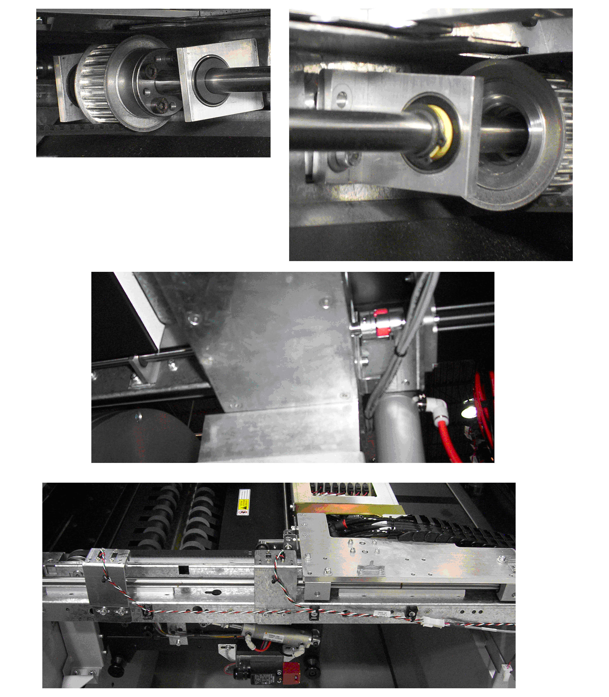
| Load table drive shaft | Check for loose or missing fasteners on the drive shaft, drive pulley, and couplings. | See error 40514 on Troubleshooting page. | |
| Load table manifold | Check for leaks and loose connections. | ||
| Load table actuators | Check for leaks. | ||
| Load table traveler | Check that the traveler is correctly aligned and that it moves freely. | The traveler is parallel to the table front beam. | See error 40514 on Troubleshooting page. |
| Load table traveler sensors | Check for damage. | ||
| Load table traveler belts | Check for damage and check tension. | Belt tension spring should be compressed to 17 mm. | |
| Plate sensors | Clean and check for damage. | Located on the front beam. | |
| Vacuum generator | Replace filter. | ||
| Plate stop fingers | Check for damage. | ||
| Up/down sensors | Check for damage. | ||
| Slip sheet sensor | Check the slip sheet bottom detection sensor calibration.
Clean sensor. |
Programming the table bottom slip sheet sensor | |
| Unload Table - CL, MCU, and APL devices only | |||
| See also Unload Table Full Service Checkup | |||
| Magnus VLF | What to Do | What to Look For | Procedure
Parts |
| Suction cups | Check for damage and clean the cups.
Check the height of the cups. Check for loose or missing cup fasteners. Check that cups move freely. |
To check height, move the cups up and measure the distance between the top of the cup and the table darts - it should be 7.5 mm ± 1 mm. | |
| Pneumatic tubes | Check for leaks or damage. | Look for kinks in the tubes. | |
| Unload table manifold | Check for leaks and loose connections. | ||
| Unload table traveler | Check that the traveler is correctly aligned and that it moves freely. | The traveler is parallel to the table front beam. | |
| Unload table traveler sensors | Check for damage. | ||
| Unload table traveler belts | Check for damage and check tension. | Belt tension spring should be compressed to 17 mm. | |
| Vacuum generator | Replace filter. | ||
| Up/down sensors | Check for damage. | ||
| Leading edge panel | Check fasteners are not loose. | ||
| Table operation | Check that table moves up/down freely. | Check for interference with the MAB. | |
| Ejector - CL, MCU, and APL devices only | |||
| Magnus VLF | What to Do | What to Look For | Procedure
Parts |
| Ejector | Check that there is no interference between the ejector fingers and the unload table darts. | See Side Ejector Alignment. | |
| Ejector | Check that it moves freely and there is no rust on ejector rail. | Install FCO CA05641A if applicable.
If ejector rail needs to be replaced, see Replacing the Ejector Rail. |
|
| Ejector actuator | Check for leaks. | ||
| Ejector home/away sensors | Check for damage and clean. | ||
| Bridge - CL, MCU, and APL devices only | |||
| Magnus VLF | What to Do | What to Look For | Procedure
Parts |
| Bridge | Check bridge height is set up correctly. | Processor height should be 950 to 1010 mm. | |
| Bridge sensors | Check for damage and clean. | ||
| Bridge | Check that it moves freely. | There should be no interference with cables or tubes. | |
| Picker - MCU devices only | |||
| See also Picker and Fetcher Full Service Checkup | |||
| Magnus VLF | What to Do | What to Look For | Procedure
Parts |
| Picker, manifold, and pressure board | Check that they are sucure. | ||
| P-cups | Check for damage and clean.
Check that white O-ring is not damaged and seated in the groove. Check tubes for leaks or damage. |
||
| P-cup swivel bar | Check for damage and that it moves freely. | Replace if necessary.
P-cup and swivel assembly upgrade |
|
| Actuator | Check tubes and actuators for leaks. | ||
| Picker manifold | Check for leaks and loose connections. | ||
| Cables | Check that all cable and connectors are sucure and not damaged. | ||
| Sensors | Check motion sensor and sensor grid for damage.
Check sensor alignment. |
Sensor grid should be 2-3 mm from the sensor's bottom (the sensor bracket may be slightly bent to achieve that). | |
| Rear hook | Check for damage.
Check that the rear hook engages correctly with the fetcher. |
||
| Reflective photo sensors | Check for damage. | ||
| Fetcher - MCU and APL devices only | |||
| See also Picker and Fetcher Full Service Checkup | |||
| Magnus VLF | What to Do | What to Look For | Procedure
Parts |
| Fetcher movement | Check for smooth movement. | ||
| Fetcher height | Check the fetcher height over the plenum. | Picker to Fetcher Alignment | |
| Suction cups | Check for damage and check that they move freely. | ||
| Pneumatic tubes | Check for damage and leaks. | Look for kinks in the tubes. | |
| Fetcher manifold | Check for leaks and loose connections. | ||
| Actuators | Check for leaks. | ||
| SS cylinder (MCU fetchers only) | Check that it moves freely in the mount block. | ||
| Fetcher deck (MCU only) | Check that the fetcher deck shaft clamping screws are secure. | ||
| Vacuum generator (MCU only) | Replace filter. | ||
| Cables | Check for damaged or loose cables and connectors. | ||
| Wedgemaster movement (MCU only) | Check that up/down movement is smooth. | ||
| Wedgemaster up sensor (MCU only) | Check alignment. | Install FCO CA06314 to upgrade the up/down sensor if necessary.
Wedgemaster cylinder block and up sensor upgrade |
|
| Flex track | Check that the cover is secured in place. | ||
| Wedgemaster inner/outer cups (MCU only) | Check alignment. | ||
| Fasteners | Check for loose or missing fasteners on the fetcher bearings, fetcher to carriage mount, and on the fetcher track guide. | Fetcher photo | |
| MCU - MCU devices only | |||
| See also MCU Full Service Checkup | |||
| Magnus VLF | What to Do | What to Look For | Procedure
Parts |
| Jackscrew nut | Check the jackscrew nut backlash. | If the nut backlash is not within the limits specified in the test document, replace the nut. | Measuring the MCU Jackscrew Nut Backlash
Replacing the MCU Jackscrew Nut |
| Jackscrew | Check that entire jack screw is lubricated. | Check if lubricator is working. If lubricator is not working, grease the jackscrew every six months with Loctite ViperLube (404-00135) | See Checking and replacing the grease. |
| Jackscrew bearings (top and bottom) | Lubricate with Alvania grease (89-0091). | ||
| Front panel | Check that there are no scratches caused by the handle. | When the handle is down, it touches the front panel. | If the handle is scratching the front panel, add rubber or tape shims (approx. 2-3 mm) between the handle damper bracket and the cart frame. |
| Sensors | Check the following sensors for debris or damage:
Lock ejector sensor. Cassette position sensor. Cassette out sensor. Cassette on cart sensor. Cart park and home sensors - also check alignment. Plenum slipsheet sensor - also check that it moves in/out freely and clean the mirror. |
Multi-Cassette Unit Setup Procedure
Replacing the MCU Cart Home Sensor Slipsheet detector 'mirror in' sensor adjustment |
|
| FPL MCU sensors | Check sensor alignment. | Multi-Cassette Unit Setup Procedure For Flush Plate Loading MCUs | |
| Cassette shutter | Check that it runs smoothly and falls under its own weight. | ||
| Cassette | Check that it moves in/out of the MCU smoothly. | ||
| Actuators | Check for leaks on the eject and cart pin cylinders. | ||
| Pneumatic tubes | Check for leaks and loose connections. | Look for kinks in the tubes. | |
| MCU manifold | Check for leaks and loose connections. | ||
| Cables | Check for damaged or loose cables and connectors. | ||
| Plenum blower | Check that it works correctly. | ||
| SSR - MCU devices only | |||
| See also SSR Full Service Checkup | |||
| Magnus VLF | What to Do | What to Look For | Procedure
Parts |
| Roller gaps | Check that the gaps are correct. | Adjusting the slip sheet bin roller gap | |
| Sensors | Check the following sensors for debris or damage:
Roller sensor. Compactor sensor. SSR bin sensor - Check sensor height and adjust if necessary. |
Bin paper counter resets when bin is pulled out of the SSR. | |
| SSR manifold | Check for leaks and loose connections. | ||
| Rollers | Check for damage. | ||
| Pneumatic tubes | Check for leaks and loose connections. | Look for kinks in the tubes. | |
Objectives: Test the system thoroughly before leaving the site! Update any/all firmware and Print Console. Note updates under Service Commands on the customer's PM Checklist.
Refer to the Control-Settings page for details of controlled releases.
| Workstation | What to Do | Procedure
Parts |
|
|---|---|---|---|
| Communication and data cables | Visually inspect the overall condition of the cables and connections between the device and the workstation.
Check that the exposed cables are protected from damage. |
Replace as required. | |
| Service Shell software | Update to the current Controlled Release version. | current version | |
| Print Console software | Update to the current Controlled Release version. | current version | |
| Head firmware | Update to the current Controlled Release version. | current version | |
| MPE firmware | Update to the current Controlled Release version. | current version | |
| Backup settings | Use BART and backup. | ||
| RAS connection | Check that the connection works correctly. | ||
| **Test operation** | |||
Complete the "Service Comments" section of the PM Checklist. For the customer's information, make a note of:
To complete the PM, the PM Checklist must be signed off by the customer and returned to Kodak.