Home | Contact Us | Submit Troubleshooting Info | Search | Help
Output | Software Solutions | Proofing | Color, Screening and Calibration | Scanning | Digital Photography | Consumables | POS
Home | Contact Us | Submit Troubleshooting Info | Search | Help
Output | Software Solutions | Proofing | Color, Screening and Calibration | Scanning | Digital Photography | Consumables | POS
Time needed: 1.5 hours (Device can be returned to customer within approximately 40 minutes)
Requirements:
| Print this document | Click the print icon  at the top of the page. |
Make sure you print it in landscape format. | |
| Safety | Before you start, make sure you are familiar with all device and laser safety concerns. | For more information see Laser safety information. | |
| External Checks | Action | Look For | Procedure or
Parts |
|---|---|---|---|
| Perform a visual check. | Visually inspect the outside of the head and the surrounding area. | Check for any device-specific issues (for example, Quantum reservoir hose integrity, stretched or pinched cables, ablation dust on the head or around the drum, and so on) | |
| Check the coolant and the coolant reservoir. |
|
|
To replace the coolant, see the Chiller page Coolant part numbers:
|
| Check dust filter on chiller or heat exchanger. | Visually inspect the dust filter. | Check for dust, debris, and damage. | Clean or replace as necessary. |
| Check that the coolant connectors have been upgraded (FCO CA09695) | Complete the procedure Replacing the Coolant Connectors on a TH2 head | ||
| Check the O-ring on the coolant hose. | Visually inspect the O-ring and hose. |
|
|
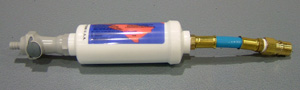
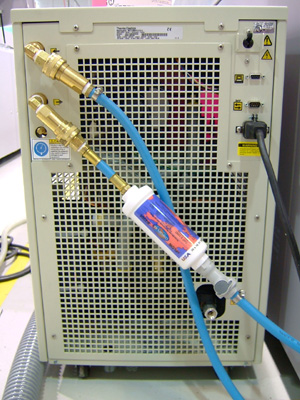
| TH2.7 only. Replace the external chiller coolant filter. | Replace coolant filter assembly 500-01665A on rear of chiller. |
|
|
| Verify the processor setup. | Ensure the processor meets operating specifications. | Check the setup specifications using the appropriate documentation. |
Note: If you are using a laptop, the results will be automatically stored there. You will need to copy them to the workstation.
| Imaging Checks | Action | Look for | Procedure or
Parts |
|---|---|---|---|
| Back up the NVS settings. | In Service Shell, run: NVSDump.spt | Make sure that the file is in the results folder. Note that location of the folder. | |
| Generate a reference plot. |
Run the standard test plot (Creo Plate Test Target). |
|
See the Creo Plate Test Target site. |
| Generate a reference stroke cal. | Create a stroke cal graph. In Service Shell, run: BeamBalance.spt |
|
| Safety | Warning: Follow Laser Safety Procedures during the next steps. | ||
| Check the laser current. |
|
|
|||||
Remove the head from the device. Note: If you are working on a Magnus 800, you do not need to remove the head. |
Turn off the device. All laser safety procedures must be followed. |
|
|||||
| Inspect and clean the debris removal nozzle. | If the device is equipped debris removal, clean the debris removal nozzle.
See: Importance of lens cleaning and debris removal |
Note: Except for Magnus 800, it is not possible to clean the debris removal nozzle if the head is on the device. |
Thermal 2 Debris Removal Nozzle Cleaning Procedure | ||||
| Inspect and clean the final window. | Clean the final window and surrounding area. You will need the lens cleaning kit (Lens cleaning kit: 04-0012B BOM). Note that you must replace the head if the window is scratched, cracked, or if the coating is coming off.
|
Note: Except for Magnus 800, it is not possible to clean the final window if the head is on the device. |
|||||
| Install the head. |
|
||||||
| Check the head installation. |
Note: If
|
To check the correct sum and error values for a Trendsetter-based device, refer to the device installation guide. For a 300-micron plate on a Lotem Quantum, expect an error of:
|
Note: On Lotem-based devices, to confirm that you’re using the correct spacer configuration for the media thickness you’re using, contact your PSS.
For more detail, refer to Z-stage spacer size identification on Lotem Quantum |
||||
| Check the edge detection. |
|
Refer to the script help for a sample graph: |
|||||
| Check the health of the focus laser diode. |
|
|
Sample result graphs: |
||||
| Tune the focus servo and check the focus actuator motion. | Run ForcePing.spt. |
|
|||||
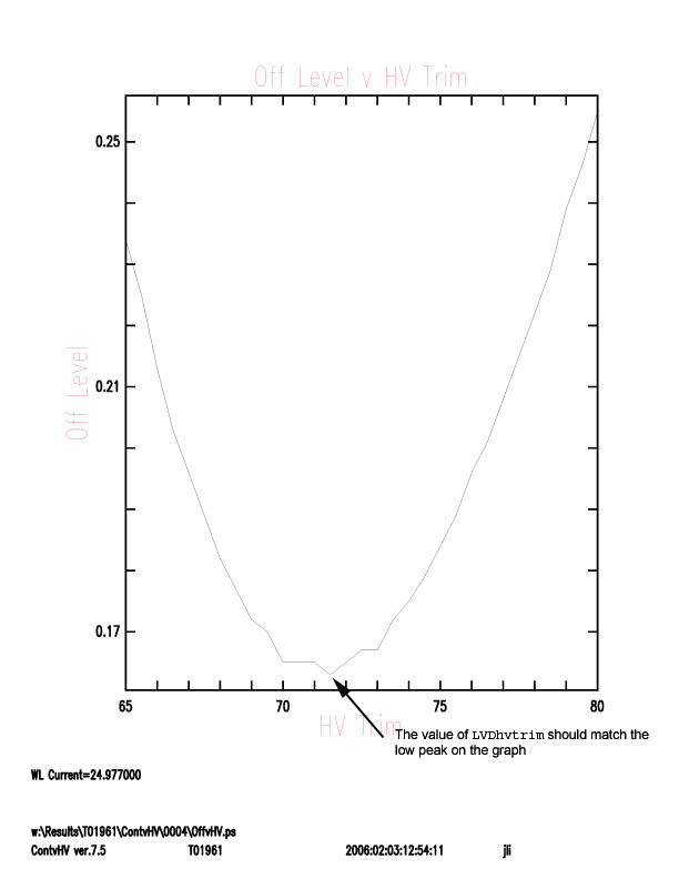
| Check the hvtrim and contrast ratio. |
|
The value of |
Note: This will give the head wider latitude for correcting the stroke, which will make it more reliable. |
||||
| Check the health of the write laser diode. |
|
If you are using a laptop the results will be automatically stored to the laptop. You will need to copy them over to the workstation. |
| Internal Checks | Action | Look for | Procedure or
Parts |
|---|---|---|---|
| Check the beam steering hold current. | Use the following procedure: Checking the beam steering hold current on a TH2 head |
If the incorrect value for the BPD hold current is used, the system will take longer to settle. This may cause a time out. Correcting the hold current will prevent this. |
View a sample of the code readout for these commands. |
| Check the ECOs/FCOs for the head. |
Check that all ECOs/FCOs have been implemented on the head. |
A list of FCOs is available on the Thermal 2 FCOs page. |
|
| Update the ldd calibrate values for the laser startup sequence. |
|
|
|
| Save the NVS settings. | In Splot or Service Shell, run: NVSDump.spt | ||
| Check that all parameter values are valid. | In Service Shell, run: parmcheck.spt |
|
| Script name | Good | Poor/Fail | Notes |
|---|---|---|---|
| BBSProfile.spt | bbsprofile_stuck_pixel.png | BeamBalance.spt | BeamBalance_good.pdf | If you get results that look like failed_1 or failed_2, escalate to the Response Centre. |
| ContvHVtrim.spt | OffvHV.jpg | The value of LVDhvtrim should match the value at the low peak on the graph. |
|
EdgeMCE.spt |
edgemce_good.pdf | edgemce_poor.png | |
FErrorvSR.spt |
FSumvSR_good.pdf | ||
FocusPI.spt |
focuspi_good.png
In this example, the maximum current applied to the focus laser is 47 mA. |
focuspi_poor.png
In this example, the maximum current value is more than 117 mA. |
To run FocusPI.spt:
|
LposStatsvLpos.spt |
LposStatsvLpos_good.png | LposStatsvLpos_poor.png |