

Home | Contact Us | Submit Troubleshooting Info | Search | Help
Output | Software Solutions | Proofing | Color, Screening and Calibration | Scanning | Digital Photography | Consumables | POS
Home | Contact Us | Submit Troubleshooting Info | Search | Help
Output | Software Solutions | Proofing | Color, Screening and Calibration | Scanning | Digital Photography | Consumables | POS
Analog Sensors |
Digital Sensors
Carriage |
Chiller |
Debris Removal System |
Engine |
Hood |
Mainframe |
Power Box |
Power Entry Box |
P-door |
Table |
Wireframe
| Item | Part Number | Reference | Notes/photos |
|---|---|---|---|
| Carriage Home | 36-3125 | ||
| Carriage Away | 36-3125 |
| Item | Part Number | Reference | Notes/photos |
|---|---|---|---|
| Chiller pressure switch kit | 510-00048 | Magnus VLF Autoloader wiring diagrams, sheet 11 | Coolant pressure switch and cable.
See FCO CA05586 |
| Item | Part Number | Reference | Notes/photos |
|---|---|---|---|
| Filter Detect Switch
(SW,Plunger,SPDT,500VAC,15A) |
15-3431 | Located in lid |
| Item | Part Number | Reference | Notes/photos |
|---|---|---|---|
| Leadscrew Temperature Sensor | 10-0967A | ||
| 6383 Drum Temperature Sensor | 10-0967A | ||
Backbone Mechanism
|
36-3125 | ||
Balance Weights
|
36-3125 | photo sensor,interrupter,slotted w/leads | |
Leading Edge Clamp (LEC)
|
36-3125 | photo sensor, reflect, modulated | |
| Plate Flyoff (PFO) Transmitter | 36-3145 | 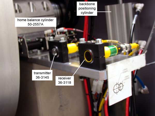 |
|
| Plate Flyoff (PFO) Receiver | 36-3118 | ||
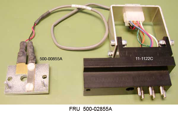
| Registration Probe Assembly
Registration probe Registration continuity switch |
500-02855A
11-1122C 500-00855A |
BOM (FRU) | DWG
BOM | DWG BOM (FRU) | DWG |
Installed on the LEC backbone. See also the Registration page.
 |
Rollers
|
36-3125 | photo sensor, reflect, modulated | |
Trailing Edge Clamp (TEC)
|
36-3125 | 10 pc | |
| TEC reed switch
200 VDC, 0.5A |
10-5065A |
| Item | Part Number | Reference | Notes/photos |
|---|---|---|---|
| Hood safety switch and lock solenoid | 172-00032 | Magnus VLF wiring diagrams for TMCE devices , sheet 5 | Door lock solenoid/safety switch assembly for the hood. It consists of the lock solenoid and switch. |
| Item | Part Number | Reference | Notes/photos |
|---|---|---|---|
| Emergency Stop Switch | 15-3474 | 3 switches; 1 front (ES2), 2 rear (ES3,ES4) | 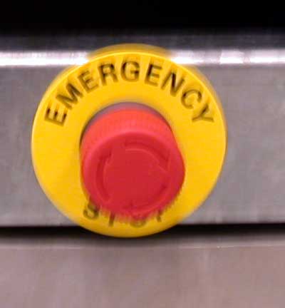 |
| Start Button 1
(ASSY,ELEC,START BUTTN,GRN LED INSERT,MTA) |
500-00261A | 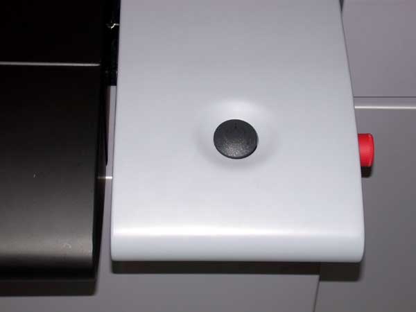
button on operator interface panel |
|
| Start Button 2
(ASSY,ELEC,START BUTTON 2,FLUSH MOUNT) |
500-00271A | 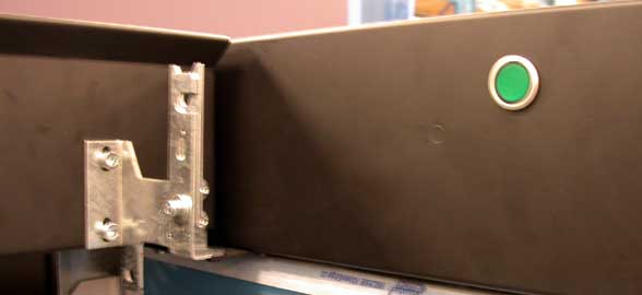
button on side of cutout |
|
| Safety Door Limit Switch kit | 518-02230A | Magnus VLF Autoloader wiring diagrams | Replaces 15-3263 by ECO CA10961. See the Omron Switch Replacement Procedure.
SSW1, rear away SSW2, hood SSW3, side rear away SSW4, side front away SSW5, side front home SSW6, side rear home SSW7, rear home SSW8, center front SSW9, center table |
See also Power box - Parts
| Item | Part Number | Reference | Notes/photos |
|---|---|---|---|
| Power disconnect switch | 11-1138A |
See also Power entry box - Parts
| Item | Part Number | Reference | Notes/photos |
|---|---|---|---|
| Main power switch | 15-3525 | 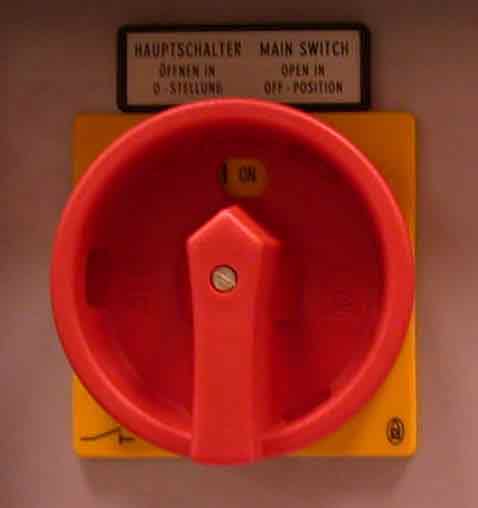 ON position 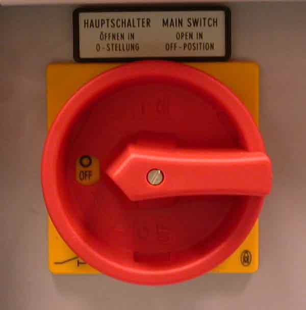 OFF position |
|
| Override keyswitch (2 position) | 15-3334 | 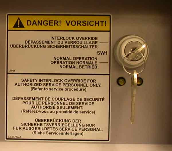 |
|
| On/off switches (3 pieces) | 15-3085 | 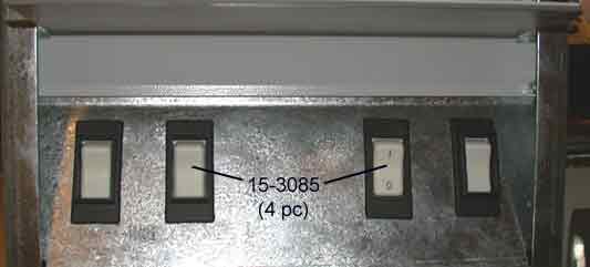
circuit breaker switches, rocker-type |
| Item | Part Number | Reference | Notes/photos |
|---|---|---|---|
| P-door Open | 10-4733A | 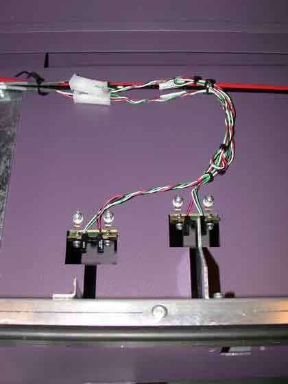
On away (motor) side of hood |
|
| P-door Close | 10-4733A |
| Item | Part Number | Reference | Notes/photos |
|---|---|---|---|
| Load ramp plate sensor | 36-3210 | 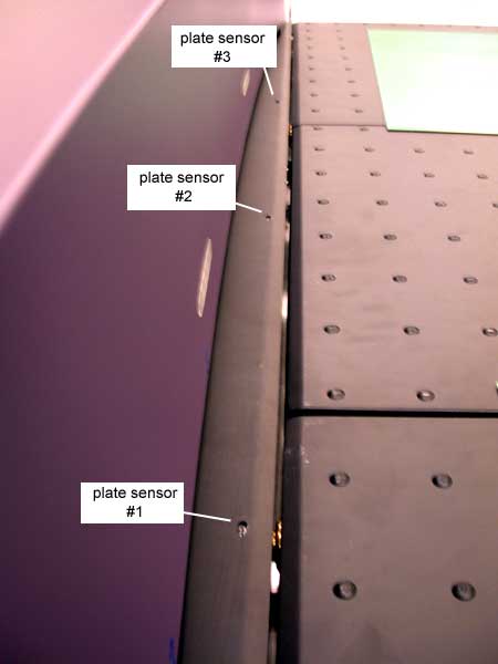
Dual plate option (3 sensors) shown |
|
| Table bottom slipsheet sensor | 36-3205 | Magnus VLF wiring diagrams for TMCE devices , sheet 15 | |
| Dropleaf switch | 10-5065A | RSW11 |
| Item | Part Number | Reference | Notes/photos |
|---|---|---|---|
| Slipsheet underside sensor and mirror | 500-01135A | BOM | DWG |