

Home | Contact Us | Submit Troubleshooting Info | Search | Help
Output | Software Solutions | Proofing | Color, Screening and Calibration | Scanning | Digital Photography | Consumables | POS
Home | Contact Us | Submit Troubleshooting Info | Search | Help
Output | Software Solutions | Proofing | Color, Screening and Calibration | Scanning | Digital Photography | Consumables | POS
Magnus VLF sensors and switches
See also Boards | Cables | Cylinders | Fuses | Motors | Power supplies
Base device | MCU | SSR
Magnus VLF at a glance 200KB (pdf) - a one-page overview of the Magnus VLF device, showing the location of sensors, switches, boards and motors.
| Item | Stored Service Parts | Reference | Notes/photos |
|---|---|---|---|
| CAB,ASSY,PHOTO INTERRUPTER,SLOTTED | 10-4982A | Cable assembly includes sensor 36-3125 - PHOTO,INTERRUPTER,SLOTTED,W/LEADS | |
| PHOTO,SENS,REFLECT MODULATED | 36-3210 | working range is 2-30 mm | |
| CAB,ASSY,REED SWITCH,NO,200VDC,0.5A | 10-5065 | notes | |
| Plate flyoff transmitter (laser) | 36-3145 | ||
| Plate flyoff receiver | 36-3118 | ||
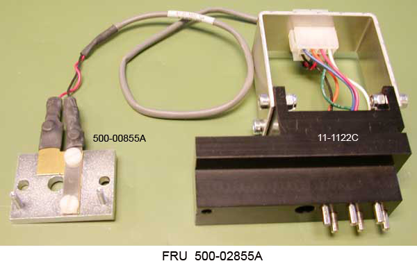
| Registration Probe Assembly
Registration probe Registration continuity switch |
500-02855A
11-1122C 500-00855A |
BOM (FRU) | DWG
BOM | DWG BOM (FRU) | DWG |
Installed on the LEC backbone. See also the Registration page.
 |
| Vacuum sensor | 172-00021 |
| Item | Stored Service Parts | Reference | Notes/photos |
|---|---|---|---|
| SSY,ELEC,SENSOR,TEMP,EH,CTP | 10-0967A | engine temperature sensor and ballscrew temperature sensor | |
| Pressure sensor located on MCE board | 1 sensor (700 kPa) | ||
| Pressure sensor board | 10-4887A-B | 1 sensor (700 kPa) | |
| Vacuum sensor located on MCE board | 1 sensor (100 kPa) | ||
| Vacuum sensor located on Genine board | 1 sensor (100 kPa) | ||
| Vacuum sensor board | 10-4581A-B | 1 sensor (100 kPa) | |
| Vacuum switches | 172-00021 | used on loadtable and unloadtable |
| Item | Stored Service Parts | Reference | Notes/photos |
|---|---|---|---|
| ES1 main power switch (25A) | 15-3525 | Magnus VLF Autoloader wiring diagrams, sheet 6 | Red rotary switch located at the back of the machine. |
| SW2 Powerbox AC power (14A) | 11-1138A | Magnus VLF Autoloader wiring diagrams, sheet 7 | Black rotary switch located on the powerbox. |
| Front hood safety switch and lock solenoid | 172-00046 | SSW12
Magnus VLF Autoloader wiring diagrams, sheet 7 |
Door lock solenoid/safety switch assembly for the front hood. It consists of the lock solenoid and switch.
500-00633A consists of the lock solenoid, switch, brackets, and cables. |
| Rear hood safety switch and lock solenoid | 172-00032 | SSW2
Magnus VLF Autoloader wiring diagrams, sheet 7 |
Door lock solenoid/safety switch assembly for the rear hood. It consists of the lock solenoid and switch. |
| Side ejector home optical switch and bracket assembly | 500-01139A | Magnus VLF Autoloader wiring diagrams, sheet 7 | Ejector home sensor and bracket assembly mounted on the ejector track. See diagram 500-00346A-D.pdf. |
| Emergency stop switches | 15-3474 | Magnus VLF Autoloader wiring diagrams, sheets 4 and 5 | Abort switches ES2 – ES7 |
| Service interlock override (SIO) keyswitch | 15-3334 | Magnus VLF Autoloader wiring diagrams, sheets 6 and 17 | The MCU and powerbox key switches are the same. The key is part number 15-3241. |
| Door interlock switch kit | 518-02230A | Magnus VLF Autoloader wiring diagrams, sheet 7 | Replaces 15-3263 by ECO CA10961. See the Omron Switch Replacement Procedure.
side front away panel SSW4 lower rear away panel SSW3 rear away panel SSW1 rear hood away panel SSW10 side front home panel SSW5 side rear home panel SSW6 rear home panel SSW7 head cover home panel SSW8 head cover away panel SSW9 bridge cover panel SSW11 |
| Chiller pressure switch kit | 510-00048 | Magnus VLF Autoloader wiring diagrams, sheet 11 | Coolant pressure switch and cable.
See FCO CA05586 |
| Thermostat 60 deg.C | 170-00024 | Magnus VLF Autoloader wiring diagrams, sheet 22 | Thermal switch for drum vacuum pump. Can be reset manually after cooling. |
| Item | Stored Service Parts | Reference | Notes/photos |
|---|---|---|---|
| PHOTO,SENS,REFLECT MODULATED | 36-3210 | Four for cassette bay detection, one for lock/eject position, one for load/unload position, two for detecting the cylinder safe and cassette retracted positions, and one in the plenum for detecting the cassette position. | |
| MCU emergency stop switches | 15-3474 | ES1-MCU; ES2-MCU | Abort switches |
| MCU 2-position level switch (semi-auto mode/manual jog mode) | 15-3536 | MCU-SW1 | On MCU service override panel 500-01150A (also called the jog button panel) BOM.
<500-1150A-A.pdf DWG> The 3 jog switches (MCU-SW2, 3, and 4) consist of 3 parts:
15-3446: Actuator (green) 15-3447: Insert (hold to run) 15-3448: Switch contacts |
| MCU pushbutton switch (hold for semi-auto) | See Notes | MCU-SW2 | |
| MCU jog up pushbutton switch | See Notes | MCU-SW3 | |
| MCU jog down pushbutton switch | See Notes | MCU-SW4 | |
| MCU/SSR service interlock override (SIO) keyswitch | 15-3334 | MCU-SW5 | |
| Flashing LEDs (2) | 10-3721A | LP1, LP2 | |
| Cart home and cart park switches | 172-00054 | MCU-SW6, SW7
Magnus VLF Autoloader wiring diagrams, sheet 17 (cart home) and sheet 18 (cart park) |
Replacing the MCU Cart Home Sensor |
| Cart locking pin sensor switches | 15-3457 | MCU-SW8, SW9, SW10, and SW11
Magnus VLF Autoloader wiring diagrams, sheet 18 |
|
| Door interlock switch kit | 518-02230A | MCU-SW8, SW9, SW10, and SW11
Magnus VLF Autoloader wiring diagrams, sheet 17 |
Replaces 15-3263 by ECO CA10961. See the Omron Switch Replacement Procedure.
MCU cassette door MCU rear right door MCU rear left door MCU side access door |
| MCU left roof safety switches | 15-3355 | LR-SW1, SW2, SW3, and SW4
Magnus VLF Autoloader wiring diagrams, sheet 17 |
|
| MCU right roof safety switches | 15-3355 | RR-SW1, SW2, SW3, and SW4
Magnus VLF Autoloader wiring diagrams, sheet 17 |
|
| Plate width sensor | 10-4652A | Connects to GENINE 3 (J10)
Magnus VLF Autoloader wiring diagrams |
 |
| Item | Stored Service Parts | Reference | Notes/photos |
|---|---|---|---|
| SSR roller extend override pushbutton switch | See Notes | SSR-SW1
Magnus VLF Autoloader wiring diagrams, sheet 20 |
Switches SSR-SW1 and SW2 consist of 3 parts:
15-3446: Actuator (green) 15-3447: Insert (hold to run) 15-3448: Switch contacts |
| SSR motor override pushbutton switch | See Notes | SSR-SW2
Magnus VLF Autoloader wiring diagrams, sheet 17 |
|
| SSR door interlock switch kit | 518-02230A | MCU-SW10, SW11, and SW12
Magnus VLF Autoloader wiring diagrams |
Replaces 15-3263 by ECO CA10961. See the Omron Switch Replacement Procedure.
SS bin rear door, SS bin cover, sheet 17 SS bin front door (local safety loop), sheet 20 |
| SSR bin cover interlock | 15-3477 | MCU-SW13
Magnus VLF Autoloader wiring diagrams, sheet 17 |
|
| SSR emergency stop switch | 15-3474 | ES1-SSR | |
| MCU/SSR service interlock override (SIO) keyswitch | 15-3334 | MCU-SW5 | Inside MCU |
| SSR Baumer slip sheet sensor | 13-5062 | Magnus VLF Autoloader wiring diagrams, sheet 18 | Sensor that defines a slip sheet between plates |
| Compactor open/close sensors and roller close sensor | 15-3355 | Magnus VLF Autoloader wiring diagrams, sheet 20 | Compactor sensors inside SSR |
| SSR roller open sensor and bin detect sensor | 36-3210 | Magnus VLF Autoloader wiring diagrams, sheet 20 | Sensor that defines an obstruction above rollers and bin presence |
| SDSR bin full sensor assy | 10-4652A | Magnus VLF Autoloader wiring diagrams, sheet 20 | |
| Slip sheet underside sensor | 500-01135A | BOM | DWG
Magnus VLF Autoloader wiring diagrams, sheet 17 |
Location:
Right eject - On the side of the home side lower MAB (cable 220-00425A). Left eject - On top of the power box frame (cable 220-00255A). |