Cause
|
|
External (to the Creo CTP system) causes of
registration problems
- Plate handling problems:
- Plates have burrs from being sheared, rough or dented edges from
mishandling, or curled edges from being stored vertically or at an
improper angle. These problems can prevent the plate from
seating correctly in the leading edge clamps (LECs).
- Debris from mishandled or improperly stored plates collects in
LEC, preventing plates from seating properly.
- [Trendsetter NEWS devices with NELA PL-T plate preloader only]
Plates carelessly stacked in the P-LT’s plate trolley can have
bent edges. The two forward guide posts can put a slight bend on
the plate edge that lines up nicely with our registration blocks
(in the case of a dual stack) and can introduce image skew.
- Plate quality control problems:
- Problems with customer’s manual punch/bender:
- Punch/bender is out of adjustment; hole or bend locations
wrong or inconsistent
- Plate is not perfectly square
- Problems on press:
Internal (to the Creo CTP system) causes of
registration problems
- Workflow:
- Improper Print Console setting for Trendsetter NEWS (Device > Edge Detect
set to Only when needed instead of Always)
- Output device:
- Image shift in mainscan direction (around the drum):
- Debris on registration blocks and/or in the LEC
- LEC gap has been set improperly.
- Picker malfunction damages plate edge, preventing it from
seating properly in LEC.
Example: Plate drops from too great a
distance, causing dents at points of contact with registration
blocks; thus, true leading edge of plate is lower than
expected.
- Image shift in subscan direction (along the drum):
- Ball nut is not tightly attached to leadscrew
- Problem with carriage drive system
- Edge detection problem:
- Plate edge has burr
- Pre-punched plate has oddly-shaped leading edge, making it
difficult for focus laser to detect true edge
- Edge detect strip contaminated with debris
- Focus laser problem
- [Trendsetter NEWS 200 dual-head only] Subscan image shift on
one head:
- NVS geometric correction parameters
mshift,
headspacing, or sshift not set up correctly
- Control cable to the thermal imaging head that has the shift is faulty.
- Dual head interface board is faulty.
- Cables from the dual head interface board are faulty.
- Image skewed on plate:
- LEC gap has been set improperly.
- Debris on registration blocks and/or in the LEC
- NVS
loadpos parameter not optimized for the
output device.
- Plate roller problems (bearing damage or too much pressure
against drum)
- Picker setup problems cause plate to be skewed on drum:
- Vacuum cups or hoses protruding from picker head, interfering
with plates
- Picker plate drop distance not set properly
- Picker vacuum cups in poor condition
- Picker NVS parameters set sub-optimally
- Picker down sensor operating incorrectly (letting go of the
plate while still in motion)
- [NEWS Dual-Bay devices with NELA preloader only] NELA PL-T
is not placing plates properly onto the NEWS device’s plate
ledge.
|
Solution
|
|
Note: If any image shifts are to be corrected by more than 1/64th
of an inch (approximately 397 microns), inform the customer of the
amount of change and confirm it will not have adverse effects on the
expected image position. They may have built templates to compensate for
the shift and those will need to be corrected after your work is done.
- Eliminate external (to the Creo CTP system) problems
Check to see whether the source of the registration problems is
external to the Creo plate imaging system.
- Inspect the punch/bender to ensure that it is not the cause of
the registration problems. If necessary, instruct the customer to
clean, repair, or readjust the punch/bender.
- Check the plates for squareness. Either check the plates with a
square, or put them back to back and butt the short ends against
a flat surface and examine the other ends. Any plate overhang at
the other end indicates possible out-of-square condition.
- Consult with the customer to ensure that the registration
problems are not caused by a problem with the press.
- Examine how the plates are being stored and handled.
Ensure that plates being used are clean and do not have burrs or rough edges.
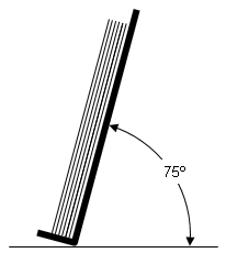
If plates are removed from their box and stored on their
edges, ensure they are stored at an angle—less than 90 degrees,
but not less than 75 degrees.
- [Trendsetter NEWS devices with NELA PL-T plate preloader only]
Ensure that plates in the P-LT’s plate trolley are stacked
carefully and do not have bent edges where they make contact
with the two forward guide posts. These can put a slight bend on
the plate edge that lines up with our registration blocks (in
the case of a dual stack) and introduces image skew.
- Eliminate Print Console/workflow-related problems
Check the Print Console/workflow settings:
- Check to ensure that the Print Console Edge Detect setting is
set to Always (not When Required). On NEWS 200 and
NEWS 150 devices, this is an option on the Device menu. On other
NEWS devices it is set in the registry. See
Print Console Sometimes Causing Subscan Shifts on Trendsetter NEWS
Devices for more information.
- Check all other relevant Print Console settings and ensure they
match what the customer expects.
- Check the customer’s files and/or templates to ensure that they are
not the cause of the image shift problem.
- Once you have eliminated external and workflow-related causes
of registration problems, you can concentrate on the output device.
- Is the registration problem a shift in mainscan direction
(around the drum)? If
so, proceed to step 4.
- Is the registration problem a shift in subscan direction (along
the drum)? If
so, proceed to step 5.
- Is the registration problem a skewing (distortion or rotation)
of the image on the plate? If
so, proceed to step 6.
- Eliminate CTP
device-related problems causing image
shift in mainscan direction
Look for problems that could cause of an image shift in the mainscan direction
(around the drum).
- Check to verify that the LEC gap has been set properly (see Adjusting the LEC Gap/Actuator Timing on the 3244 Engine).
- Verify
loadpos (MCE) or lepos (MPE)
parameter and ensure that it is optimized for the output device
(again, see Adjusting the LEC Gap/Actuator Timing on the 3244 Engine).
- Is there debris on registration blocks and/or in the LEC? If so, clean
the contaminated parts, and then see if you can find the source of
the debris and prevent it from accumulating again.
- Inspect all LEC components (clamps, pivot blocks, cylinders,
actuator) and check for excessive deflection in the center of each
clamp. Replace and adjust as necessary.
- Is there a picker malfunction that results in damage to the plate’s
leading edge, preventing it from
seating properly in LEC?
For example, does the plate drop from too great a
distance, denting the leading edge at the points of contact with registration
blocks?
If so, adjust the picker so that the plate does not
drop from too great a height. See
Leading
edge of plate is dented when released onto the registration pins.
- GC parameters:
- Eliminate CTP
device-related problems causing image
shift in subscan direction
Look for problems that could cause an image shift
in the subscan direction (along the drum).
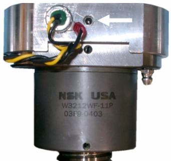
- Is the ball nut assembly tightly connected to the flex tube
on the carriage? If not, use a hex key to back off the
setscrew on top of the ball nut assembly until it no longer
makes contact with the carriage’s flex tube. Then, tighten
the setscrew ¼ turn past the point that it just makes
contact with the flex tube. This is approximately 4.6 N·m
(40 lbf·in) of torque.
- Are there burrs or roughness at the edges of the plate? If
so, ensure that the customer is handling and storing the
plates correctly (see step 1d, above). If
the plates themselves are substandard, advise the customer
to discuss this issue with the plate vendor.
- Is the customer using pre-punched plates that have unusually-shaped leading edges,
which make it difficult for focus laser to detect the
plate’s true edge? (See example, below.)
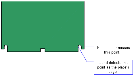 If so, and the output device is a Trendsetter NEWS 200 (with
thermal 2 heads), adjust the edge sr parameter so that the
focus laser can detect the true plate edge. See
Calculating the Edge Surface Reflectivity for more
information. If the NEWS device uses a thermal 1.x head,
- Is the edge detect strip contaminated with debris? If so,
clean or replace it.
- Is there a problem with the focus laser? See:
TH1.7x:
Setting Focus Parameters in the field (TH1.X)
TH2:
Troubleshooting focus errors
- GC parameters:
- Run a plot 100 on the home side plate, and make any
necessary adjustments to the subscan shift to get the
registration mark to the 1 x 1-in. location. For more
information (and for information on adjusting the
mainscan shift and rotation parameters), see
step 6a, below.
- [Trendsetter NEWS 200 dual-head only] If the image shift
occurs on one head, check to see if any of the following
components are faulty:
- Eliminate CTP device-related
problems causing image skew
Look for problems that could cause the image to be skewed (distorted
or rotated) on the plate:
- GC parameters:
- Run a plot 100 on the home-side plate, and make any
necessary adjustments to the mainscan and subscan shifts
to get the registration mark to the 1 x 1-inch location.
- Check for rotation and correct if necessary.
- Using the above adjustments as the reference, image a
plot 100 on the home-side plate, then reload it on the
away side and image a plot 114.
- Make the necessary adjustments to align the mainscan,
subscan and rotation parameters to match the home side.
- If there are multiple machines, use this first machine
as a reference, and align subsequent machine home and
away plate positions gc to match.
For more information on setting geometric correction
parameters, see:
- Check to verify that the LEC gap has been set properly (see Adjusting the LEC Gap/Actuator Timing on the 3244 Engine).
- Verify
loadpos (MCE) or lepos (MPE)
parameter and ensure that it is optimized for the output device
(again, see Adjusting the LEC Gap/Actuator Timing on the 3244 Engine).
- Is there debris on registration blocks and/or in the LEC? If so, clean
the contaminated parts, and then see if you can find the source of
the debris and prevent it from accumulating again.
- Inspect all LEC components (clamps, pivot blocks, cylinders,
actuator) and check for excessive deflection in the center of each
clamp. Replace and adjust as necessary.
- Check the plate roller for
damaged bearings or too much pressure against the drum. It must spin
freely.
- Picker setup:
- [NEWS Dual-Bay devices with NELA preloader only] Check that
the NELA PL-T is placing plates properly onto the NEWS
device’s plate ledge. The PL-T plate drop height must be set
properly (5 mm to 10 mm is good) and the NEWS device’s
separator arms must not be sticking out too far. If the
plate drop height is too high, the plate can get badly
skewed in the bay, and then fail to drop squarely into the
LECs. Also, preloader machines that return an unused plate
back into the plate stack in the trolley can damage the lead
edge and introduce image skew.
For more information on the
Trendsetter NEWS Dual-Bay option, see
Dual Bay option
information.
|

