Home | Contact Us | Submit Troubleshooting Info | Search | Help
Output | Software Solutions | Proofing | Color, Screening and Calibration | Scanning | Digital Photography | Consumables | POS
Home | Contact Us | Submit Troubleshooting Info | Search | Help
Output | Software Solutions | Proofing | Color, Screening and Calibration | Scanning | Digital Photography | Consumables | POS
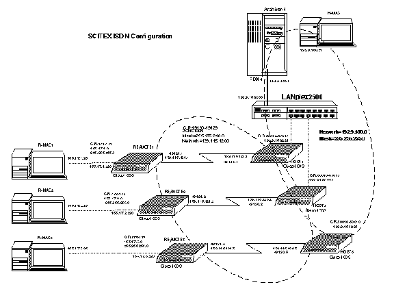
CreoScitex provides an integrated hardware and software solution: the FileTrak Over ISDN which provides ISDN connections between remote sites. The CreoScitex FileTrak Over ISDN, consisting of Cisco 1003/4 routers at both the Host and the Remote sites, enables the rapid transfer of data between Archiver installed bases and their clients.
The above Figure graphically explains the Scitex FileTrak Over ISDN.
The CreoScitex FileTrak Over ISDN consists of Cisco 1003/4 Routers installed at Archiver sites and their remote clients, allowing client access to the Archiver database using the MAC FileTrak application in order to browse the Archiver and to allow AppleShare for drag and drop and PSImage retrieval.
The Cisco 1003 and 1004 Routers provide Integrated Services Digital Network (ISDN) capability in a small, desktop Router. The Routers connect small, remote sites with Ethernet LANs to WANs.
The main difference between the two Routers is that the Cisco 1004 Router includes an integrated network termination 1 (NT1) device and the Cisco 1003 Router does not. The ISDN service provider supplies the NT1 connection worldwide, except in North America, where the NT1 device is supplied by the customer. Therefore, the Cisco 1004 Router is for use in North America, and the Cisco 1003 Router is ideally suited for use elsewhere.
The CreoScitex North American subsidiary (STA) will supply the Cisco 1004 Router unit within their operating region. All other subsidiaries will distribute the Cisco 1003 Router.
From the front, the outward appearance of both units is the same:

Front View of the Cisco 1003/4 Router
The following is a list of the LEDs on the front panel:
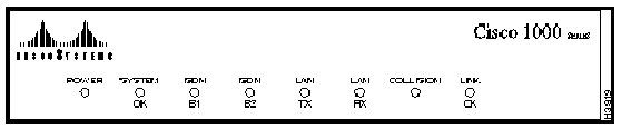
Front Panel of the Cisco 1003/4 Router
The LEDs indicate the current operating condition of your Router. The following table describes the LEDs:
| LED | State | Description |
| Power(green) | On steadily | 12 VDC is being supplied to the Router and the internal DC-to-DC converter is operational. |
| Off | Power is not reaching the Router. Verify that the power supply is plugged into the wall receptacle, and that the cable from the power supply to the Router is connected. If the power supply is working properly, the Router might be defective. |
|
| System OK(green) | On steadily | The Router has passed the power-on diagnostic tests and is working properly. |
| Blinking once per second | The system LED blinks once per second when running startup diagnostics or decompressing the software image. If the system LED continues to blink after the startup sequence, the Router is in ROM monitor mode. | |
| Off | An error condition has occurred. Disconnect the power cord; then reconnect it to re-establish power to your Router. If the LED remains off, contact your system administrator. | |
| ISDN B1 (green) | On steadily | The call on the BRI B channel 1 line is connected. |
| ISDN B2(orange) | On steadily | The call on the BRI B channel 2 line is connected. |
| LAN TX(orange) | Flickering | The Ethernet LAN connection is transmitting data normally. |
| LAN RX(green) | Flickering | The Ethernet LAN connection is receiving data normally. |
| Collision(orange) | On | Ethernet data collisions are being detected. Occasional collisions are normal. If they happen often, contact your system administrator. |
| Link OK (green) | On | The Router senses the Ethernet link integrity signal, indicating normal operation. |
From the back, the Routers look the same except that the ISDN BRI (RJ-45) port is labeled "ISDN S/T" on the Cisco 1003 Router and "ISDN U" on the Cisco 1004 Router.
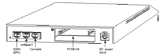
Back view of the Cisco 1003/4 Router
Additionally, the product name - Cisco 1003 or Cisco 1004 - is stamped on the chassis at the upper left side (not shown).
Both Routers include the following connectors:
For more information, see the Cisco 1003/4 Router Installation Guide, or follow the instructions on the UniverCD (interactive, on-line library of product information from Cisco systems) supplied with the unit.
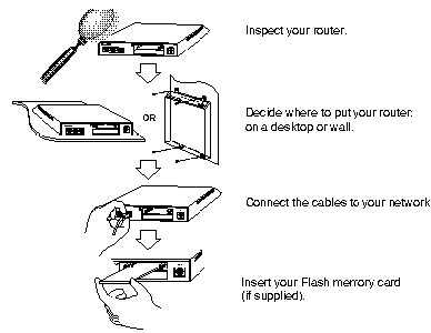
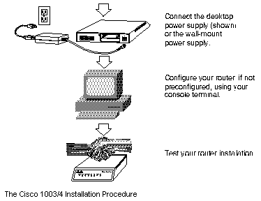
The following is a step-by-step list that summarizes the installation procedure for the Cisco 1003/4 Router.
You are now ready to configure the system
The installation procedure for the Cisco 1003/4 is summed up in the figure below. For more information, see the UniverCD, or the Cisco Systems Installation Guide enclosed with the Router. The Cisco 1003/4 Installation Procedure
Making BRI Connections
Using the appropriate cable, connect the Basic Rate Interface (BRI) port to the Integrated Services Digital Network (ISDN) through the NT1. The common carrier will provide the NT1 connection worldwide, except in North America, where the NT1 is customer owned. The NT1 is an ISDN Channel Service Unit/Digital Service Unit (CSU/DSU).
Warning: Network hazardous voltages are accessible in the BRI cable. If you detach the BRI cable, detach the end away from the Router first to avoid possible electric shock. Network hazardous voltages are also accessible on the network processor module in the area of the BRI port (RJ-45 connector) even when power is turned OFF.
The BRI network processor module supports point-to-point operation at OSI Layer 1. Only one source (the transmitter) and one sink (the receiver) are actively transmitting at any time in each direction at an S interface (CCITT specification I.430 section 3.1).
The BRI module does not support a point-to-multi-point wiring configuration.
Because the BRI module does not support point-to-multi-point configuration, D channel
access procedures are not implemented.
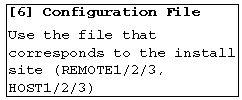
TFTP configuration files are provided for the host and remote Cisco 1003/4 routers:
The following steps are taken to correctly configure the Cisco Router:
 ,
the program continues to the next stage. For ease of use, the lines seen on
the terminal screen are printed in Courier.
After installing the Router, it requires an initial configuration.
Each time it is switched on, the individual Router unit will search for and obtain its configuration from its NVRAM, its flash memory or by manual configuration.
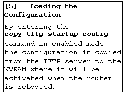
If a configuration file is already resident in the NVRAM in the Router, this will be loaded automatically. By entering the copy running-config startup-config command in enabled mode,
the configuration is saved in NVRAM.
The Cisco Router unit is configured with its IP address via a terminal (or a Mac/PC
running a Terminal Emulation Program) connected via the RS232 (serial port), by changing
the following default settings at the command line.
The following is seen on the terminal screen:
_____________________________________________________________
Cisco Internetwork Operating System Software
IOS (tm) 1000 Software (C1000-BY-M), Version 11.0(7.3), MAINTENANCE INTERIM SOFTWARE
Copyright (c) 1986-1996 by Cisco Systems, Inc.
Compiled Tue 16-Apr-96 17:39 by vprasad
Image text-base: 0x02004000, data-base: 0x0225A430
cisco 1000 (68360) processor (revision D) with 3584K/512K bytes of memory.
Processor board ID 02404960
Bridging software.
Basic Rate ISDN software, Version 1.0.
1 Ethernet/IEEE 802.3 interface.
1 ISDN Basic Rate interface.
8K bytes of non-volatile configuration memory.
2048K bytes of processor board PCMCIA flash (Read/Write)
Notice: NVRAM invalid, possibly due to write erase.
--- System Configuration Dialog ---
At any point you may enter a question mark '?' for help.
Use ctrl-c to abort configuration dialog at any prompt.
Default settings are in square brackets '[ ]'.
Would you like to enter the initial configuration dialog? [yes]:
Configuring global parameters:
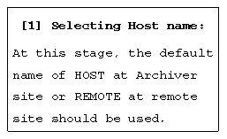
Enter host name [Router]: REMOTE [1]
The enable secret is a one-way cryptographic secret used instead of the enable password
when it exists.
Enter enable secret: a
The enable password is used when there is no enable secret and when using older software
and some boot images.
Enter enable password: seisdn
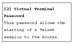
Enter virtual terminal password: scisdn [2]
Configure SNMP Network Management? [yes]: n
Configure DECnet? [no]:
Configure AppleTalk? [no]:
Configure IPX? [no]:
Configure IP? [yes]:
Configure IGRP routing? [yes]: n
Configure RIP routing? [no]: n
Enter ISDN BRI Switch Type [none]: n
Configuring interface parameters:
Configuring interface BRI0:
Is this interface in use? [yes]: n
Configuring interface Ethernet0:
Is this interface in use? [yes]:
Configure IP on this interface? [yes]:
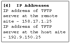
IP address for this interface: 158.17.1.220 [3]
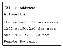
Number of bits in subnet field [0]: 8
Class B network is 158.17.0.0, 8 subnet bits; mask is 255.255.255.0
_____________________________________________________________
The following configuration command script was created:
hostname REMOTE
enable secret 5 $1$EmtJ$jbUuD2IaTH73oawQwPFtP.
enable password seisdn
line vty 0 4
password scisdn
no snmp-server
!
ip routing
no appletalk routing
isdn switch-type none
!
interface BRI0
shutdown
no ip address
!
interface Ethernet0
ip address 158.17.1.220 255.255.255.0
!
end
Use this configuration? [yes/no]: y
Warning: No ISDN switch-type defined. No calls possible.
Building configuration...
[OK]
Use the enabled mode 'configure' command to modify this configuration.
Press RETURN to get started!
%LINEPROTO-5-UPDOWN: Line protocol on Interface Ethernet0, changed state to up
%LINK-3-UPDOWN: Interface BRI0, changed state to up
%LINK-3-UPDOWN: Interface Ethernet0, changed state to up
%LINK-5-CHANGED: Interface BRI0, changed state to administratively down
%LINEPROTO-5-UPDOWN: Line protocol on Interface BRI0, changed state to down
%IP-5-WEBINST_KILL: Terminating DNS process
%SYS-5-RESTART: System restarted --
Cisco Internetwork Operating System Software
IOS (tm) 1000 Software (C1000-BY-M), Version 11.0(7.3), MAINTENANCE INTERIM
SOFTWARE
Copyright (c) 1986-1996 by cisco Systems, Inc.
Compiled Tue 16-Apr-96 17:39 by vprasad
REMOTE>
=-=-=-=-=-=-=-=-=-
Creating the TFTP Server
The default configuration must now be copied to the TFTP server. Run the TFTP application
and copy the remote default config file to the TFTP folder found in the Preference folder
inside the System folder of the Mac.
To edit an existing configuration file:
Note: The configuration files should not be corrupted. The configuration files should be saved under a different name so as not to overwrite the original configuration. A copy of the configuration files should be saved by the CreoScitex Installation Engineer for CreoScitex records.
version 11.0
no service pad
service timestamps debug uptime
service timestamps log uptime
service udp-small-servers
service tcp-small-servers
!
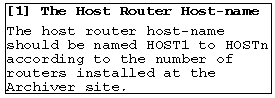
hostname HOST1 [1]
!
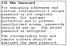
enable secret 5 [2]
$1$y3nA$J2bGH/jCXG3h4RzwIaQ5Q.
enable password seisdn
!
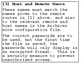
username HOST1 password 7 0809637D3D48
username REMOTE1 password 7 0014121517[3]
appletalk routing
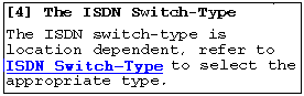
isdn switch-type basic-net3 [4]
!
interface Ethernet0
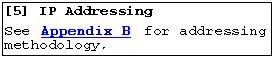
ip address 192.9.150.221 255.255.255.0 [5]
appletalk cable-range 50010-50010 50010.44
appletalk discovery
!
interface BRI0
ip address 139.115.120.1 255.255.240.0
ip access-group 101 in
ip access-group 102 out
encapsulation ppp
dialer load 30
appletalk cable-range 49120-49129 49120.1
appletalk zone ~ISDN
appletalk access-group 650
no appletalk send-rtmps
dialer map appletalk 49121.1 name REMOTE1 broadcast
dialer map ip 139.115.121.1 name REMOTE1 broadcast
dialer load-threshold 150 either
dialer-group 1
compress stac
ppp authentication chap
!
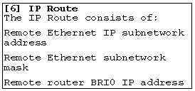
ip route 158.17.1.0 255.255.255.0 139.115.121.1 [6]
logging trap debugging [7]
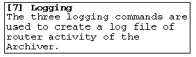
logging facility local6
logging 192.9.150.1 [8]

access-list 100 permit ip any any
access-list 101 permit tcp any any eq 7099
access-list 101 permit icmp any any
access-list 102 permit tcp any eq 7099 any
access-list 102 permit icmp any any
access-list 601 permit cable-range 171-171 broadcast-deny
access-list 601 deny other-access
access-list 650 permit nbp 1 type AFPServer
access-list 650 deny other-nbps
access-list 650 permit other-access
appletalk static cable-range 171-171 to 49121.1 zone Remote1
appletalk ignore-verify-errors
dialer-list 1 list 601
dialer-list 1 list 100
!
line con 0
line vty 0 4
password scisdn
login
!
end
version 11.0
no service pad
service udp-small-servers
service tcp-small-servers
!
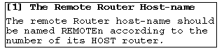
hostname REMOTE1 [1]
enable secret 5 [2]
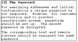
$1$y3nA$J2bGH/jCXG3h4RzwIaQ5Q.
enable password seisdn
!
username HOST1 password 7 095C4F1A0A [3]
username REMOTE1 password 7 0014121517 [3]
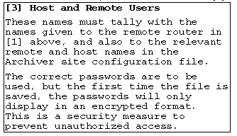
appletalk routing
isdn switch-type basic-net3 [4]
!
interface Ethernet0
ip address 158.17.1.220 255.255.255.0 [5]
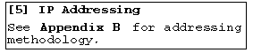
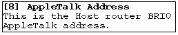
appletalk cable-range 171-171 171.62
appletalk zone Remote1
!
interface BRI0
ip address 139.115.121.1 255.255.240.0
encapsulation ppp
load-interval 30
appletalk cable-range 49120-49129 49121.1
appletalk zone ~ISDN
appletalk access-group 651
no appletalk send-rtmps
dialer map appletalk 49120.1 name HOST1 broadcast 5082199
dialer map ip 139.115.120.1 name HOST1 broadcast 5082199
dialer load-threshold 150 either dialer-group 1
compress stac
ppp authentication chap
!
ip http server
ip route 192.9.150.1 255.255.255.255 139.115.120.1 [6]
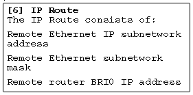
access-list 100 permit ip any any
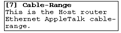
access-list 601 permit cable-range 50010-50010 [7] broadcast-deny
access-list 601 deny other-access
access-list 651 permit nbp 1 object Ripro1
access-list 651 permit nbp 1 type AFPServer
access-list 651 deny other-nbps
access-list 651 permit other-access
appletalk static cable-range 50010-50010 [7] to 49120.1 [8] zone RIPRO1
dialer-list 1 list 100
dialer-list 1 list 601
!
line con 0
line vty 0 4
password scisdn
login
!
end
The ISDN dial numbers are configured as part of the dialer map under the BRI interface. Usually, the PTT provides the end user with three ISDN dial numbers: one dial number per each B channel and one dial number that allows connection to both B channels on the BRI interface (case A). In this case it attempts connection to B0 and if found to be busy, it will connect to B1. This is the default configuration.
Alternatively, the PTT can provide you with only two ISDN dial numbers, one for B0 and one for B1 (case B).
The default configuration is:
dialer map appletalk 49120.1 name HOST1 broadcast 5082199
dialer map ip 139.115.120.1 name HOST1 broadcast 5082199
Using a text editor, you should change the dial number (5082199) to the ISDN number of the Archiver site to which you would like to connect.
Following the change save the configuration and load the router with the configuration file (see Loading the Configuration from the TFTP Server).
Case A:
dialer map appletalk 49120.1 name HOST1 broadcast 1234567
dialer map ip 139.115.120.1 name HOST1 broadcast 1234567
The configuration stays the same as the default configuration expect for the different ISDN dial numbers.
Case B:
Each B channel should have is own line (i.e. four dialer maps, two per each channel).
dialer map appletalk 49120.1 name HOST1 broadcast 1234567
dialer map appletalk 49120.1 name HOST1 broadcast 1234568
dialer map ip 139.115.120.1 name HOST1 broadcast 1234567
dialer map ip 139.115.120.1 name HOST1 broadcast 1234568
The recommended ISDN standard used outside of North American is EuroISDN (basic net3). CreoScitex uses EuroISDN as its default configuration. In the case that EuroISDN is not supported by your local PTT, you must modify the configuration as follows:
HOST1> en
Password:
HOST1#
HOST1# conf t
Enter configuration commands, one per line. End with CNTL/Z.
HOST1(config) #isdn switch-type
basic-1tr6 1TR6 switch type for Germany
basic-5ess AT&T 5ESS switch type for the U.S.
basic-dms100 Northern DMS-100 switch type
basic-net3 NET3 switch type for UK and Europe (EuroISDN)
basic-ni1 National ISDN-1 switch type
basic-nwnet3 NET3 switch type for Norway
basic-nznet3 NET3 switch type for New Zealand
basic-ts013 TS013 switch type for Australia
ntt NTT switch type for Japan
vn2 VN2 switch type for France
vn3 VN3 switch type for France
HOST1(config)# isdn switch-type basic-net3
New switch-type will not take effect until reload
HOST1(config)# exit
HOST1#
%SYS-5-CONFIG_I: Configured from console by console
HOST1#
HOST1# reload
System configuration has been modified. Save? [yes/no]: y
Building configuration...
[OK]
Proceed with reload? [confirm]
Because the Archiver sends IP traffic to remote sites, you need to configure IP static routing on the Ripro server.
To configure static routing on the Ripro server:
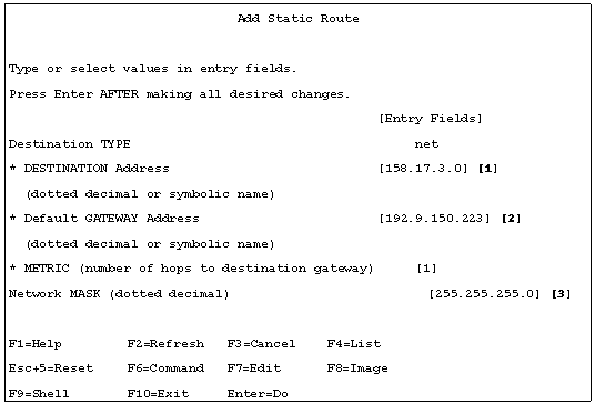
Repeat the above procedure for each remote site at each Archiver site.
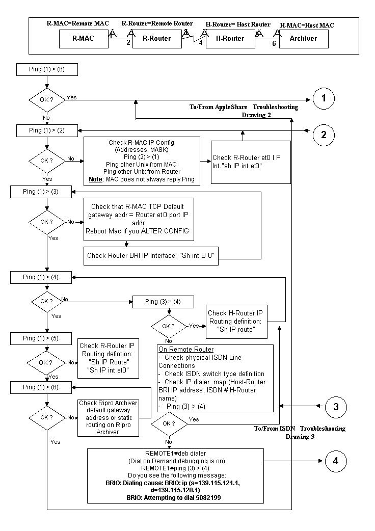
Note: If you encounter difficulties in adding static routes, refer to Troubleshooting.
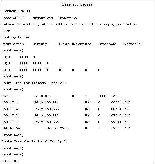
Displaying all Routes
To display all static routes for the Archiver:
You have to adjust the AppleTalk configuration of the Router to the Ripro.
The Host Router's Ethernet port has a default cable range of 50010-50010. Refer to How to configure Ripro Server AppleTalk for more details.
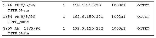
All ISDN activity on the HOST router is recorded to a log file on the Archiver. Logging these events is performed using the syslog deamon.
Enabling the Log File
To enable logging events to a log file:
To activate the log file, reboot the server.
Viewing the Log File
To access the log file directly from the Mac you can create a symbolic link to the file
from the Ripro Application volume.
To create the link enter the following commands on the Archiver:
# cd /scitex/version/macprogs
# ln -s /scitex/version/logs/isdn.log
Following this command you will be able to access the file from the Mac by mounting the Ripro Application volume.
The following is a sample log file:
Using the netconf utility, configure the Ripro to compliment the configuration of the Cisco Router.
Since every AppleTalk network needs to have a "seed" router, if the Ripro is not configured as a router, i.e., there is only one Ripro interface to one AppleTalk and no other AppleTalk router on network, you have to configure the Cisco Router as the seed router.
To configure the Cisco Router as the seed router:
| interface Ethernet0 | |
| ip address 192.9.150.221 255.255.255.0 appletalk cable-range 50010-50010 appletalk zone Ripro1 appletalk zone Ripro2 appletalk zone Retouch |
|