Dolev 4press - Assemblies
Carriage Motion Assembly
Overview
The Stepper Motor is attached to the Lead Screw Assembly on the
Imagesetter left side. This motor controls revolution of the lead screw during exposure.
The Stepper Motor may require replacement due to malfunction.
The Stepper Motor operates the Leaad Screw which moves the Dynamic
Optics Carriage.
Disassembly
On the Imagesetter left side, separate the Stepper Motor from the
Lead Screw Assembly by removing its four (4) hex screws and disconnecting its electrical
connector.
Assembly
Reverse the disassembly procedure described above.
Carriage
Assembly
Overview
| Affected Models: |
Dolev 4press |
| Affected Assemblies: |
Lead Screw Assembly |
| Affected Parts: |
Lead Screw, Spinner Motor |
| Special Tools Required: |
None expansion |
General Description
The lead screw is located at the heart of the Imagesetter, in the
center of the V-block which runs lengthwise along the Imagesetter drum. It is used to move
the Dynamic Optics Assembly through the Imagesetter drum during exposure.
The lead screw may require replacement due to damage caused during
operation, excessive wear, or improper manufacture.
- From the Utilities menu, move the Dynamic Optics Carriage to its end
position (EP) in the Imagesetter.
- Power down the Imagesetter.
- Open both left and right Imagesetter doors.
Releasing
Lead Screw
- Remove the inertia damper located on the right side of the
Imagesetter by removing its two (2) hex screws.
- Release the three (3) recessed hex screws securing the lead screw
from the Imagesetter right side. You will need an extension wrench to access these screws.
You do not to remove these screws completely.
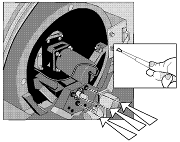
- On the Imagesetter left side, separate the Stepper Motor from the
Lead Screw Assembly by removing its four (4) hex screws and disconnecting its electrical
connector.
- Remove the Dynamic Optics chain holder by removing its two (2) hex
screws. Allow the chain holder to rest alongside the V-block.
- Disconnect the Dynamic Optics Assembly electrical connector by
removing its securing screw.
- Remove the four (4) hex screws securing the Lead Screw Assembly to
the left side of the V-block.
- Slowly withdraw the Lead Screw Assembly from the Imagesetter. Be
careful not to disturb the Dynamic Optics carriage.
Assembly
Reverse the disassembly procedure described above.
Description
The home position detector is assembled on the lead screw bearing
plate. It is located on the optomechanical assembly guide beam, or carriage. Its function
is to mark the starting point of the carriage movement.
Checking
- Enter the diagnostics program.
- Select UTILITIES.
- Select the Adjustment menu.
- Select H.P. Calibration. It will send the carriage to Home position
in fast motion. It reads the micro steps offset.
Replacement
Diassembly
- Power off the imagesetter using the control panel ON/OFF switch.
- Open the left and right service doors.
- Disconnect the home position detector cable connector on the left
side of the machine.
- Dismantle the two screws that hold the home position detector base to
the guide beam and pull the assembly out.
Assembly
- Assemble the home position detector on the guide beam. Try to keep
the flag on the carriage passing through the center of the detector and try to keep it
located as close as possible to the previous detector location. Tighten the two screws.
- Connect the cable connector back to the home position detector.
- Enter the diagnostics program. Select UTILITIES. Select Adjustment
menu. Select H.P. Calibration. It will send the carriage to Home Position in fast motion.
It reads the micro steps offset.
The test passes if the offset is between 125 and 375. Correct the
location of the H.P. by trapping on the home position detector with the back of a
screwdriver until the reading received is in the middle of the correct zone.
Disassembly
- Disconnect the end position detector cable connector on the right
side of the machine.
- Dismantle the two screws that hold the end position detector base to
the base plate. Remove the assembly.
Assembly
- Assemble the end position on the guide beam. Try to keep the flag on
the carriage passing through the center of the detector and try to keep it located as
close as possible to the previous detector location. Tighten the two screws.
- Connect the cable connector back to the end position detector.
- Activate the DIAG/UTIL. From the Mechanics/Carriage menu choose F.P.
(Feed Position) Detector. Correct the location of the end position detector by trapping on
the detector with the back of a screwdriver until the reading received is in the middle of
the correct zone.
|

