Background
|
|
The objective of performing a laser uniformity test is to
enable calibrating the laser intensity for all 12 or 24 lasers so that
they are uniform.
Note: Test results do not depend on the
plate type, size, or thickness, so this test can be performed on any plate
type that the customer uses.
|
Procedure
|
|
- Load a plate.
- In Lotem Controler, change the Laser Factor From Host Enable
parameter value to 0:
- In the hardware tree, select Others and then right-click
Lotem 400V.
- In the Properties: 400V dialog box, double-click +EXPOSE.
- Change the Laser Factor From Host Enable parameter value
to 0, and then click Apply.
- Open the Lotem Calibration dialog box:
- For Lotem 400 Xpose—on the Xpose Utilities panel, double-click
LotemCalib.
- For Lotem 400—proceed as follows:
- In Brisque, on the CDE panel, double-click Devices.
- In the Output Device Handling dialog box, select Plate Setter
> Lotem > Lotem400.
- On the Operation panel, select Lotem Calibration.
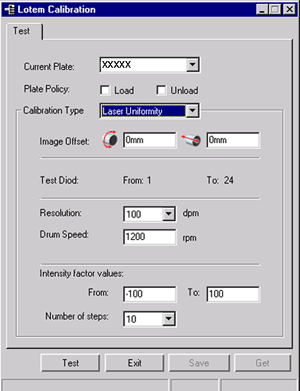
- In the Lotem Calibration dialog box (example shown for Lotem Xpose),
in the Calibration Type list, select Laser Uniformity.
- Select the plate type:
- For Lotem Xpose—in the Current Plate type dropdown list
- For Lotem 400—in Media
- Define the Plate Policy:
- Load plate—Automatically loads a new plate before the
test begins. If you clear this option, an already-loaded plate is
used, and you can reuse a plate for additional calibration tests.
- Unload plate—Automatically unloads the plate after the
test. You must load another plate for additional tests. If you clear
this option, you can reuse the plate for additional calibration tests.
- Define the Image Offset values:
- Horizontal offset—the value around the drum in mm
- Vertical offset—the value along the drum in mm
If you use the same plate for several tests, use different offset values
for each test.
Note: The (0,0) offset coordinate is located at the upper-left
corner of the plate.
- In the Test Resolution list, select 100.
- In the Intensity factor values area, type 0 in both
the From and the To boxes.
- In the Number of steps list, select 1.
- Click Test to initiate the laser uniformity test according
to the settings.
- Develop the plate and examine the results. The results appear on the
plate in a column of 12 squares for Lotem 400 small, and 24 squares
for Lotem 400 non-small.
- Use a densitometer to measure the dot percentage of each square.
- Calculate the average of all the measurements.
- Find the square whose measurement is closest to the average value,
and define the dot percentage of this square as the target dot percentage.
- Define the factor for each diode, as follows:
0.5(Target dot % - measured dot %).
Then round off this value to the closest integer. For example:
- If the target dot % is 55 and you measured a dot % of 46.5 for
diode #0, the calculated factor value for this diode is
(55-46.5)/2=4.25
In the factor table, the value for diode #0 is 4.
- If the target dot % is 55 and you measured a dot % of 60.6 for
diode #1, the calculated factor value for this diode is
(55-60.6)/2=-2.8
In the factor table, the value for diode #1 is -3.
Note: Write down the factors and save them.
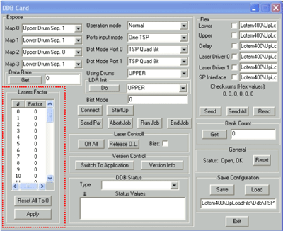
- After calculating all the diode factors, type these values in the
factor table, as shown, and then click Apply.
If the results are not satisfactory, continue with step 19.
- Repeat the test as described in steps 10 to 12, and write down the
factor for each diode.
- Repeat step 18, and 19 if required.
- For each diode, analyze the previous dot % measurment, the factor
you gave it, and the current dot % measurement. Use these three factors
to calculate a better estimate, as shown in the following table:
| |
Diode #0 |
Diode #1 |
| Target dot % in first test |
55.0 |
|
| Dot % in first test |
46.5 |
60.6 |
| Factor for second test |
4 |
-3 |
| Target dot % in second test |
58 |
|
| Dot % in second test |
60.3 |
61.0 |
| Factor for third test |
3 |
-5
|
The factors for the third test are calculated as follows:
- For diode #0, the dot % in test 2 is higher than the target dot
% in test 2. Therefore, the factor was decreased from 4 to 3.
- For diode #1, the dot % in test 2 is still higher than the target
dot % in the second test, so the factor is changed from -3 to -5.
After performing several tests, you should succeed in bringing the dot
% measurements for the diodes to within ±2%.
|

